

 The Aquatint Screen
As described in the technique of heliogravure, it is necessary to have some screen to illuminate the gelatinized paper or carbon tissue in order to bypass the use of a resin or asphalt aquatint. The resin or asphalt powder is applied by means of the called resin or aquatint boxes, where the product, finely grounded, is mechanically shaken and let fall down over the copper plate surface. The variety in size of particles and the random probability of landing onto the copper allows for a random spatial distribution. In this way, an infinity of little particles fall over the plate in a sort of network with a shape and distribution completely unpredictable. The lack of determinism in the probability of spatial distribution and size pattern applies for that is called stochastic screen. Observing under magnification and in words of Luis Hernández (3), there can be observed that can be called islands, channels and lakes. The islands represent the copper areas protected from the ferric chloride attack because the gelatin will be tanned or hardened, while the channels and lakes are the areas that will be etched by the acid.
Although the results obtained with this method can achieve exceptional quality depending on the methodology employed, some key parameters for the success are not so easy to standardize. Between them can be cited the control over the particle size, the aquatint box volume, the mechanical system to shake the particles, the waiting time before put the plate into the box, the time of particle deposition over the plate, the melting method and the final cooling procedure. An alternative consist in the use of a screen digitally generated and filmed over high contrast photographic film. This allows for a reproducibility in the method less depending on variety in praxis.
The general method includes to generate a bitmap image in which the proportion of white (transparent in the film) and black pixels matches the desired density, that is usually around a covering of 50%. During the first exposure, the transparent spaces in the screen allows the UV light to pass and to harden the gelatin. After the gelatin is transferred to the copper plate and the non hardened gelatin is washed away, the ferric chloride will attack the part of the copper represented by the black pixels in the digital screen. The etching will be proportionally deeper relating with the time the copper is immersed in the acid. Beside this etching in depth, there is also a more or less important lateral etching that progresses beyond the perpendicular of the hardened gelatin, in such a manner that at the end of the process the etched area will be a bit more large that expected. If the etching is prolonged beyond some limiting time, the lateral etching will connect some channels eliminating the little islands. All that concludes in bigger lakes that will difficult the ink retention during the plate wiping, producing the so called open bite in the shadow areas of the image. Then, preparing a digital file to make a random or stochastic screen, some questions must be taken into account:
- The file resolution (ppi) determines the size of the smallest island or the narrower channel present in the screen.
- The initial gray value of the image decides the final coverage or density of the screen. That is, the proportion between the white and black pixels in the binary image.
- Remember that the black pixels constitute the area that will be finally etched and the lateral etching will be added to some extent to this initial black area. In turn, the lateral etching depends on the total etching time and the strength of the etching baths.
Screen Resolution
As has been explained, the file spatial resolution will determine the smallest island present in the image. In a first approximation, smaller elementary units in the screen difficult the detection by the observer and preserve little image details. The resolution of a given system breaks down from its weakest step and up to the copperplate etching in our case, this is the screen. Beyond the copperplate, the weakest point affecting the resolution of a print is the paper fibres. The little detail visible in the etched plate depends on the screen resolution regardless the positive image resolution. Nevertheless, a high resolution screen can be accompanied by some risks that is important to evaluate. In first place, the illumination system employed will translate the screen to the gelatin in a different way depending on its properties: collimated, punctual or diffused. The collimated systems generate a parallel beam of rays in a such way that they arrive completely perpendicular to the vacuum press glass. This kind of illumination is incorporated in professional devices as the NuArc, Amergraph and other industrial UV light assemblies. Actual punctual systems are not possible in the real world but a little bulb far away enough from the vacuum press can behave as reasonably punctual. Finally, diffuse systems are generally constituted by the batteries of fluorescent tubes.
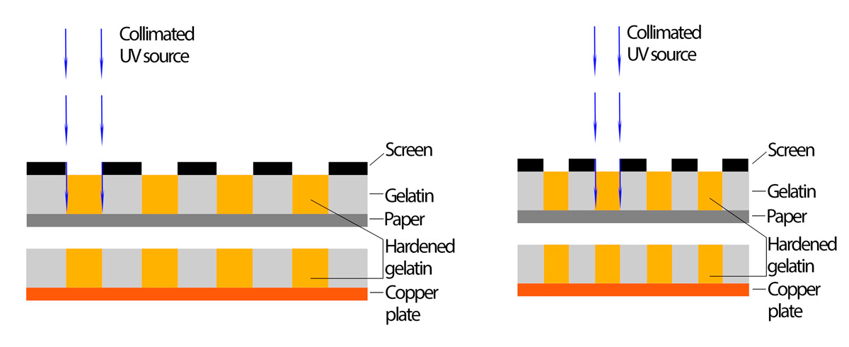
The Figures 1, 2 and 3 show comparative idealized schemes of the above described light sources behaviour and relating with two different screen resolutions. In the Fig., 1 can be observed as for collimated sources the translation of the screen dimensions into hardened gelatin is perfect regardless the area of the plate and the size of the screen elements. The only one constriction is the total area that the source is able to illuminate as a function of its design. Then, this system do not show any difficult to faithfully translate the screen scheme.
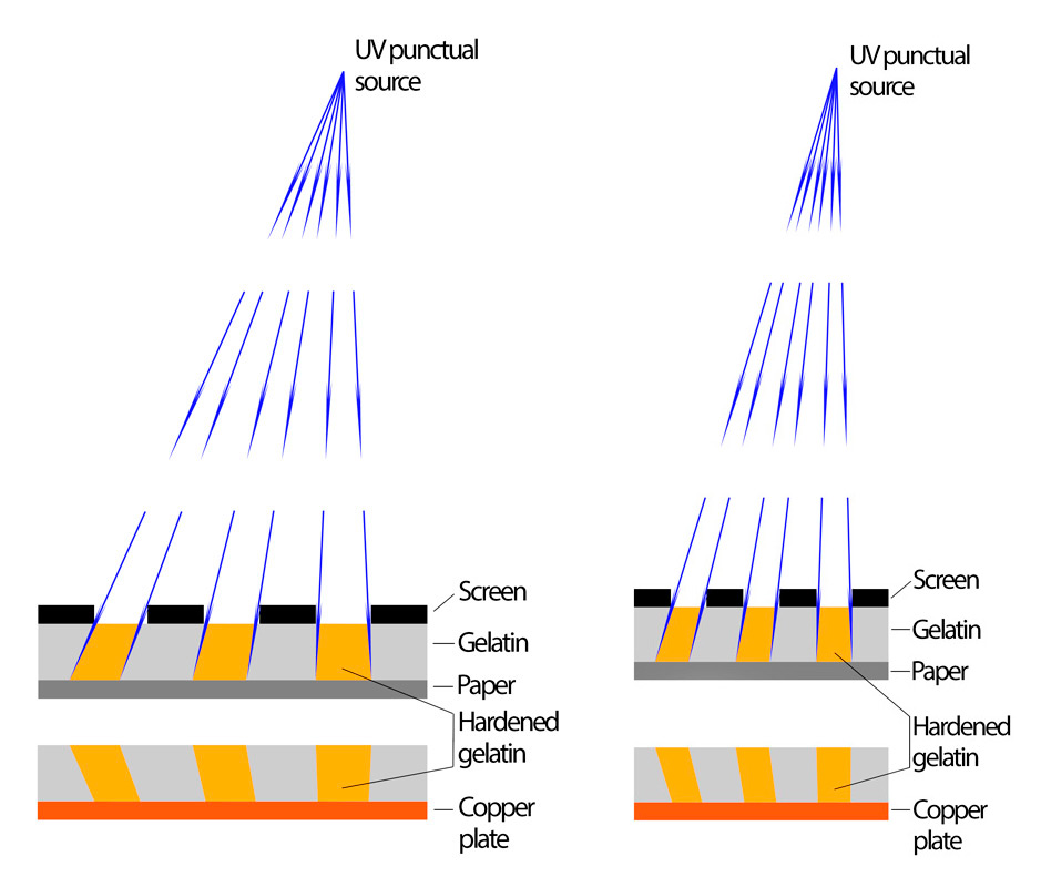
In the Fig., 2 there is shown the effect caused by a punctual source. It can be observed as the far is the position from the center of illumination, the more the screen footprint changes in position and size into the gelatin thickness. There is a reduction in size for the hardened gelatin parts and then is changed the relationship between those parts and the preserved by the opaque areas in the screen. Nevertheless, even in the exaggeration of the example, the effect is not so important if the bulb is small in size and sufficiently away from the vacuum press.
Finally, the Fig., 3 shows as a diffused source can harden the gelatin even under the opaque element of the screen, mainly in the case of high spatial resolution. This system allows to illuminate large spaces with a relatively reduced price and a low range of energy consumption. Nevertheless and attending to its constrains, the diffused systems are really only useful for the illumination of positive images.

The second question is related with the lateral etching. Depending on the method employed to binarize the original image that will be used as screen, the channels will be closer between them and that implies that the lateral etching will easily connect it. This provokes the apparition of larger lakes that, if are large enough, will result in open bite on shadow areas. Another related question is that if the screen resolution is very high to improve the visibility of detail in the image, the screen and image respective exposure times must be carefully controlled. In an ideal situation, the transparent areas of the screen must generate a thickness of hardened gelatin equally in depth to those generated by the positive highlights. A lack in this equality cause a crenelate relief in the final washed gelatin. Because of capillarity and viscosity relationships, this crenelate relief can difficult the penetration of the ferric chloride. This is specially important with high resolution screens. The high is the spatial resolution, the narrow are the crenelate holes.
Although I haven’t found any reference about that, it is possible that the non-hardened areas have a minimum size beyond which any ferric chloride dilution will be able to penetrate. The physical implications of the ferric chloride penetration in the gelatin resist is very complex and out of the knowledge of who write this text. Nevertheless, the capability of liquid penetration in narrow spaces is closely related with viscosity. A high resolution screen, with narrow spaces between hardened resist, may need a more diluted concentration of ferric chloride to allow its penetration in the shadow areas. This can alter the correct progression of the etching. The preservation of clean highlights, will conduct in this case to an insufficient etching of the shadow areas. Then, it is necessary a balanced compromise between the screen resolution, the exposure times and the total etching duration.
All that considerations implies that the screen generated by digital means would be as little as possible but avoiding the upper explained constriction. A little screen is not only useful to avoid its detection by the naked aye of the observer, but improves the visibility of the image detail. Attending to the historic evolution, it could be enough creating a screen imitating the rosin aquatint aspect and size.
To the extend of many texts consulted by the author, there are no numerical data published about the average size of the rosin aquatint particles. David Morrish (4), in his book Copper Plate Photogravure, Demystifying the Process, recommends to use screen with a spatial resolution between 250lpi (lines per inch) and 300lpi. Those resolutions correspond to a particle sizes of 102µm and 85µm respectively. It is specially significant that the first figure is coincidental with the average resolution of the naked eye at the distance of distinct vision. It seems that those figures come from the spatial resolutions used in the printing industry for the regularly spaced half-tone screens, but are not actually related with the rosin particle size. If the image positive transparency is generated by a digital inkjet printer and attending that its maximum actual resolution is of 1440dpi, we can say that the screen to be employed could have the same or lower spatial resolution. This is because a higher screen resolution cannot improve the positive quality coming from the inkjet printer. Taking the values recommended by David Morris, we can consider multiple values as 600ppi, 900ppi or even 1200ppi, always below the limiting resolution of the inkjet printer.
Screen Scheme
If the goal is to emulate the structure obtained by the rosin grain, that we need is to prepare a bitmap image with a random distribution of the respective white and black pixels. There are two possibilities to do that. The first one is to begin with a smooth greyscale image which pixels have the grey value corresponding to the density or ink coverage desired. Applying some quantity of noise to that image will conduct to a random grey value distribution. If now a threshold of grey value 128 is applied, all pixels are converted to white (255) or black (0) depending on its original value being respectively over or below the medium grey value of 128. The key in this method is how to adjust the noise tool and it depends on the software used. No matter the software and tool employed to do that, the final black ink coverage must be measured. For instance, if we want a final coverage of 50%, the original image would be a smooth one with all its pixels of a 128 grey value. After the application of noise and threshold, the average value of the resulting image must be 128 or a very close value. This indicates that the number of black and white pixel is equal; then, a 50% of black coverage. In many digital image processing software, this can be corroborated by the histogram data.
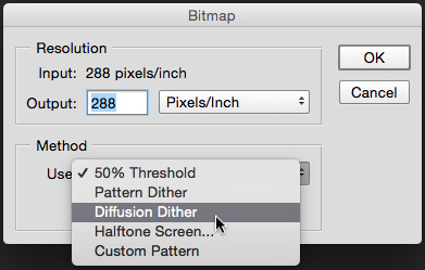
The second method available is to begin in the same manner as previously described but applying a binarization by mean of a stochastic screening in frequency modulation (FM). In Adobe Photoshop, the option is the menu Image > Mode > Bitmap and to choose the option Diffusion Dither (Fig., 4). This system applies a binarization of the original gray values to 0 or 255. This binary conversion is applied to the first pixel in the upper/left corner of the image and then the error committed depending on its original grey value is diffused over the subsequent pixels an so on, until the last pixel in the bottom right corner of the image.
In a pictorial image, this kind of binarization provides a new image version where the tone is represented by a more or less dense groups of black pixels over a white background. The black pixels represent the ink in the final printing system and the white ones are the paper color. From a smooth image of constant gray value the final version is composed by a random distribution of white (255) and black (0) pixels that emulates the original image average grey value or density. Although Adobe Photoshop don’t explain which is the algorithm employed, it is surely a version of the so called of Floyd Steinberg (2). Even though the several software implementations available incorporate modifications of the original algorithm to avoid the artefact, this binarization system tends to show a checker board result when is applied to a smooth image of medium grey value of 128. Then, if we want to obtain a final coverage of 50%, it is necessary to begin with an image which grey value approximates but don’t equals the value of 128. Conversely, 117 or 138 can be taken, corresponding respectively with black coverings of 55% and 45%. The Fig., 5 shows the resulting binarizations by the two described methods and taking flat images with a constant grey value of 138 (45%) in both cases. At left, by means of applying a noise generation algorithm; at right, with the diffusion dither from Adobe Photoshop. It is necessary to realize that the parts of the plate that will be etched corresponds with the black pixels in the screen only if it is filmed as positive.
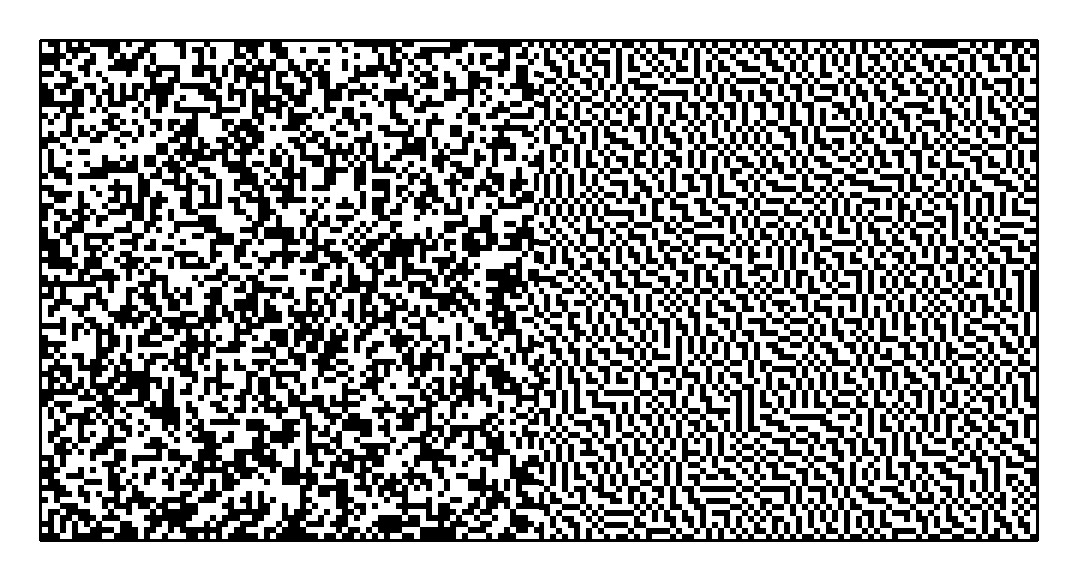
Observing the screens shown in the Fig., 5, the obtained by mean of applying noise (left) is more similar to the traditional schemes published from the classic rosin aquatint, with islands, channels and lakes of several sizes and random distribution. Conversely, the created by diffusion dither (right) shows also a random distribution but there is an almost constant value of the separation between islands, channels and/or lakes. This constant separation is in general of one pixel and equals the file resolution value. In both schemes there can be seen also isolated individual pixels. Those individual pixels are the smallest ink point or paper space in the final stamp and are too the most prone to be affected by the lateral etching.
This lateral etching, if occurs, will not affect in the same manner to the two screens. With the screen generated applying noise, shown at left, the lateral etching will enlarge the size of the original lakes and then will increase the risk of open bite in the shadow areas. With the screen shown at right, by diffusion dither, the risk of lateral etching is also present but with a more predictable behaviour and with the same level of risk all over the image. Then, the system by means of diffusion dither (right) would present less risk of uncontrolled or locally generated open bite. This constrain with the method shown at left, imitating the rosin aquatint, is explicitly explained by H. M. Cartwright (1) about the classic rosin aquatint, “… and give difficulties in etching because the elements vary so much in size with random distribution and the finer ones tend to be etched away.”
Attending to this different structure, the screens generated by application of noise would be used with files of higher resolution in order to control the final size of the original lakes, that are always several times bigger than the image resolution. This allows to avoid the risk derivative from the lateral etching. In both cases, with noise or diffusion dither, the image resolution must be adjusted attending to some before mentioned issues:
- Risk of detection by the naked eye of the observer.
- Behaviour relating with the illumination system.
- Reasonable ferric chloride penetration window. The need for a diluted solution to penetrate the shadow areas, can result in a premature penetration of the image highlights.
Physical Support of the Screen
After the file is prepared with one of the two described methods, there are three ways to take the screen over a physical support, laser printer, inkjet printer of photographic quality or filming over photographic high contrast film. Laser printer is the cheapest option but presents some difficulties derivative from its usual low spatial resolution. Schemes with spatial resolution higher than 450ppi could be poorly reproduced.
The inkjet printer of photographic quality can achieve actual resolutions of 1440dpi and even 2880dpi in some units. This allows for a fine reproduction of screens with spatial resolutions up to 1200ppi, but the system tends to create diffused edges constituted by ink drops of different opacity. This compromises the reproduction of the screen scheme and alters the initial covering or balance between white and black regions in the screen. There are available in the market some RIP (Raster Image Processor) for those printers that corrects this problem common in Graphic Arts with halftone work, but the price is quite elevated for a non commercial use. A cheaper RIP as the QuandToneRIP provided by Roy Harrington is very interesting for the calibration of the positive image printing but cannot completely solve this kind of problem with screens.
The most reliable method is to send the file to a pre-press service bureau that develops the file onto photographic film using a high resolution image-setter. For a reasonable price, sizes up to DIN-A2 and bigger can be obtained. The resulting black parts are constituted by metallic Silver depositions of high density (4.0OD – 5.0OD) and the edge resolution is nearly perfect. Additionally, the black metallic silver is more resistant to the UV radiations than the inkjet ink. The only one problem is that those services are progressively substituted by the so called Computer To Plate (CTP) technology and there is no future for it at medium term. May be in the next years the systems to print the screen with inkjet printer will improve enough. In the meanwhile the service bureau is available, the option is to provide a number of screens to cover the work over a reasonable period of time. Taking care in handling, a screen over a photographic film can be a long lasting item.
Screen Exposure
There are several authors that recommend an exposure time for the screen, that in most cases is expressed as a percentage of the positive exposure time, previously determined. In most cases, the recommended exposure time exceeds that of the positive attending to provide a thicker resist than the obtained in the image highlights. Nevertheless, it is difficult to advise a concrete time or percentage provided that the respective physical support are different and consequently is different too its transparency to the UV light. If both the screen and the positive transparency have been obtained over photographic film, the respective base+fog opacity may be relatively equal and then a slightly longer exposure time for the screen is correct. In the other extreme, if the screen is done over photographic film and the positive, for instance, inkjet printed on Pictorico OHP transparency, the exposure time for the screen, even being shorter than the applied to the positive, can provide a thicker resist. It is therefore necessary to check the respective densities by a suitable densitometer or indirectly by experimentation, always for a given light source.
References
1. CARTWRIGHT, H. M. (1961) Ilford Graphic Arts Manual, Volume 1-Photoengraving. Ed. Ilford Lted, Ilford, Essex.
2. Diffusion Dithering Algorithms
3. HERNÁNDEZ, Luis (2010) El Heliograbado por el Procedimiento Talbot-Klíč – Antecedentes, uso y principios para el control del tono. Tesis Doctoral, Dir. José M. Guillén. Universidad Politécnica de Valencia-Facultad de Bellas Artes-Dept. de Dibujo.
4. MORRISH, D. and MacCALLUM, Marlene (2003) Copper Plate Photogravure, Demystifying the Process. Ed. Focal Press, Burlington MA.

4 Replies to “Heliogravure II – Stochastic Screen”