

As time goes by and practice evolves, a sight to back shows a lot of changes from last post of mine on this technique in 2017. Here is a succinct list of my current method for heliogravure or photogravure on copperplate. Readers of former posts will find minute changes in several phases side by side with other important ones. As in many other posts is this blog about technique, the text do not pretend to be a detailed procedure guide, nor a dogmatic assertion on how things must be done. In the same manner that I have changed several times the decision about how to solve and proceed on a given problem, the practiser may find a better way to do, a different approximation to what a photogravure must be or a simply preferred procedure. The steps here described correspond to the use of inkjet printed positive transparencies, Dragon Gravure carbon tissue from Cape Fear Press, Potassium Bichromate as a sensitizer, digitally designed screen, mirror polished copperplates and etching in Iron (III) Chloride.
Sensitizing. The sensitizing of the carbon tissue by Potassium Bichromate is done by brush in order to save solution and also to avoid contamination. Stored in plastic syringes, the dilution at 4.5% is always fresh. Syringes are kept in refrigerator at 6ºC (Fig., 1) until just before use. Sensitized tissue is adhered onto a piece of transparent plexiglas and is dried under a cold air flow until spontaneous detachment (aprox. 1h). Then is placed into a saturated humidification chamber (RH = 99%) during 30min in order to standardize the tissue humidity before exposure.
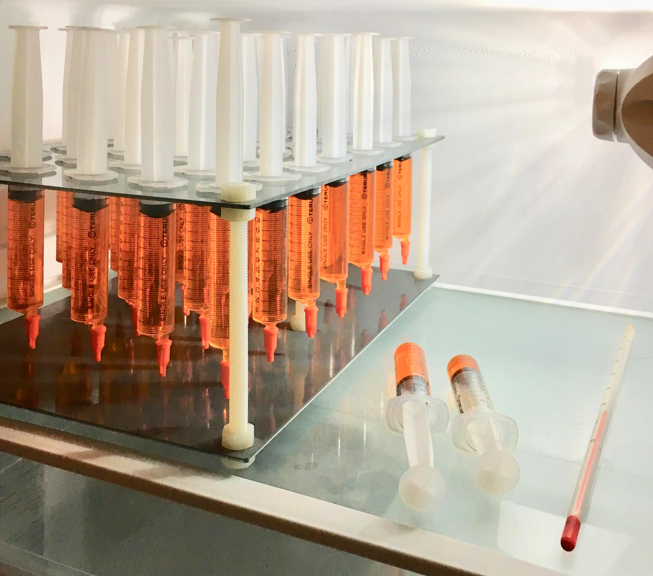
Figure 1
Ultraviolet Light Source. At the beginning of my path in photogravure, I had used a metal halide point light source at 75cm on top of the vacuum contact press. Constrains were changes in output power over time, need for a stabilization time, heat and an excessive wide range of emitting wavelengths which do not help in the control of contrast. Amergraph and NuArc devices incorporate an output power controller solving the ageing of lamp. Nevertheless, its main purpose in the printing industry it is not bothered by excessive contrast as it is definitely necessary in photogravure.
A second option was a flat panel of UV LED. This solution was effective because of almost no heat emitted and instant full power emission. The constrain was a longer than necessary wavelength (395 – 405nm). This was effective in terms of gelatin tanning in thickness but with poor strength do not supporting the etching without the apparition of some devils here and there.
Current light source is a bank of six Philips Black Light Fluorescent Tubes. Heat emission is very low and they emit a peak of UV-A at 365nm (Fig., 2), equalling the peak of sensitivity for bichromated gelatin. The only constrain is a minimum of two minutes necessary to achieve an uniform output. Contrast is best gently controlled because its specific emission wavelength. I have no detected any change in print detail nor in sharpness. By the moment, it is my preferred option only pending to try the LED with an emission peak at 365nm.

Figure 2
Screen. The screen was prepared as described in Heliogravure II – Stochastic Screen. Digitally prepared in Photoshop, it is then printed on B&W high contrast photographic film in a pre-press service bureau.
Positive Transparency. Once the picture is edited and finished on the computer display, it is sent to an EPSON R3000 inkjet printer driven by QuadToneRIP (QTR) that helps to control the density of the output. Transparency is Pictorico OHP from Mitsubishi. The printer uses only the Photo Black, Yellow and Light Black inks in order to obtain a suited UV blocking performance as is described in Printing Negatives or Positives for Alternative Processes. The density of the positives is adjusted by a QTR profile to a range of 1.4OD read in Visible Spectrum and 1.3OD read through a Wratten Tri Blue 47B filter. After a lot of tests in many different ways, I’m no longer using any kind of linearisation curve on the printed transparency. As bibliography states, the response of the bichromated gelatin to the UV light is linear and the etching action of the Iron (III) Chloride on Copper it is also. Then, the linearity of the final print must be controlled by the etching scheme.
Conversely and in order to obtain the print blacks as dense as possible, the full greyscale of the positive image is treated in two separated parts. Blacks from 0 to 26 gray value and the rest from 26 to 255 gray value. This special processing have been done both in Photoshop by two different ways or in QTR with the available profile commands. Currently, Photoshop controlling is found easier and reliable. Additionally, working at Photoshop processing level, it can be fine tuned for each image. The consistence and density of blacks have been really improved by this system.
Exposure Through the Screen and the Positive Transparency. The Test Image (Fig., 3) incorporates a greyscale of eleven steps with figures indicating the pixel grey value of each step. The use of a test with a pictorial image beside the greyscale helps in educate the perception in image viewing and then comparing that with what the plot says. Figures are important but sight has also its own contribution. Using this test, I determine the best suited exposure time for the positive transparency in first place. To do so, expose and adhere the carbon tissue on a piece of Pictorico or clean thin glass, then read the transmitted density of the eleven steps. The complete scale must be clearly differentiate and there must be a slight sign of gelatin thickness in the step corresponding to the Black (0 grey value). Experience demonstrates that provided the presence of the complete greyscale in form of gelatin thickness, the exposure should be maintained as short as possible.

Figure 3
Factors affecting the necessary exposure time are:
-
- Concentration of Potassium Bichromate in the carbon tissue.
- Humidity level of the carbon tissue.
- Type of UV light source and wavelength(s) it is emitting.
- Intensity of light source.
- Distance.
- Glass thickness in the vacuum contact press.
- Use or not of thin Mylar sheet between the positive transparency and the carbon tissue.
- Time
Being for a given installation easy to standardize the first seven, the only variable is Time.
Once the positive transparency exposure time is determined, the exposure time necessary for the screen can be calculated. As it is also well stated in Bibliography and because of too complex reasons to be fully explained here, the exposure of the screen must be slightly higher than that intended for the positive. Remember that “exposure” is not necessarily “time”. As the base respective supports of the screen and the positive are different, the actually necessary exposure time through the screen might be a bit shorter or longer than the used through the positive transparency. The actual exposure time must be derived by trial or reading the respective transmitted densities in the UV range. Density readings in the VIS range could be erroneous because the transparency to different radiations can be very different for many materials.
Lay-down and Washing (Development). The properly exposed carbon tissue is adhered on the copperplate in a bath of Ethanol 15%, Isopropyl-alcohol 15%, Water 70%. I have tried Ethanol, Methanol, Isopropyl-alcohol and many mix of them with no significant advantages in adherence difficulties or air bubbles trapped between the carbon tissue and the copperplate. A couple of preventions have been realized as very effective: More than 50% of water in the mix and previously chilled in the refrigerator (≈ 6ºC). After drying the excess of liquid with paper towels and 5min of resting, I wash in running water at 45 – 50ºC for a minimum of 5min or until there is no red pigment evidence in the washing water. Finally, a wash of 5min with gently rocking of tray in Ethanol 40%, Isopropyl-alcohol 40%, Water 20%, rinse and drying with a hair-dryer set at hot air (≈ 60ºC). Once completely dried and being protected those parts of the plate not to be etched, rest the plate for 30min into the saturated humidifying chamber (RH ≈ 99%) before etching.
Etching. This is the part of the process I have changed more from time to time. As above explained, there is not a linearisation curve applied to the positive and then, the linearity of grey values in the print is highly dependable of the etching scheme. After again a lot of trials, I have decided that two baths of Iron (III) Chloride are enough for a well linear greyscale in the print. The etching is fully controlled by looking at the greyscale attached to all plates and through a magnifying glass. A resumed synthesis is as follows:
-
- The two etching baths have a 3.5ºBé in difference.
- The concentration of the first bath depends basically of the gelatin thickness in the black step of the greyscale. I adjust it in order to have an etching beginning after between 1m 30s and 2min of immersion.
- Baumé degrees are precisely read out with a precision of ±0.1ºBé (20ºC).
- Etching baths temperature is maintained at 20ºC ± 0.2ºC.
- Trays are continuously and gently rocking.
- The etching time begins when etching actually occurs at the black step of the greyscale (0 grey value).
- The time elapsed to visually detect the beginning of the etching in the step of 26 grey value, serves to determine how long the plate will be etched in the first bath. A factor is applied to calculate it. At the end of this time, the plate is passed to the second bath.
- The time elapsed to visually detect the beginning of the etching in the step of 230 grey value, serves to determine how long the plate will be etched in this second bath. This is determined depending on the importance of highlights in each given picture.
Notice that I deliberately do not publish figures here. Because of so many variables affecting how the gelatin resist arrives finally conditioned to the etching step, I think it is not possible extrapolate values and times between workshops and practitioners. The only aim of this summary is to help to establish a reliable criteria for those looking for an (almost) standardized procedure, linear in greyscale and consistent in black density. Three goals not so easy to achieve.

Congratulations Carles
LikeLike
Thank you Jaume. Seguim…
LikeLike
Extraordinario!!!!
LikeLike
Muchas gracias Jesús!
LikeLike
Great contribution, thank you Carles!
LikeLike
Thank you for follow José!
LikeLike