
 Heliogravure has some particular characteristics that don’t facilitates the system calibration in order to arrive to a sort of WYSIWYG. Working from a film negative, it is a different experience if the user prints the negative on photographic paper before to perform the heliogravure or passes directly to the heliogravure. In the first option, what we want to see in the heliogravure print is conditioned by what we have seen in the photographic positive print. Therefore, the making of the transparent positive has a goal previously determined. If instead, the heliogravure is done using the photographic negative with no other intermediate than the positive transparency, then the judgement about tone and contrast will be preferentially performed at the final stage when the print come out of the press. Those aspects of the work method are not trivial, since we are always conditioned by the previous vision we have of a given image. Additionally, the photographic print paper may or may not have different reflection properties relating with the heliogravure final print paper. If both the photographic and the heliogravure prints are done over, for instance, satin neutral white papers, the perceptive experience looking at the two prints may be very close to one other. Conversely, using a premium glossy baryte paper for the photographic positive print and since most of heliogravure printing papers have matt surfaces, will probably conduct to a highly different perceptive experience when both are observed under the same lighting level.
In a different way, for those working from digital image files, it is sometimes painful to get on the print what is seen on the computer screen. It is necessary to note that in reality, this an unachievable goal. With a given printing black ink, it may be possible to achieve a dense and opaque black that allows for the same visual perceptive experience as when you look at a “0” black in the computer screen. Conversely, the whitest paper that you can use in heliogravure printing cannot reflect as much light as the white “255” transmits through the computer screen. Therefore, some preventions must be taken in the attempt to transport our experience of looking at the screen to the imprinted piece of paper. This is not an exclusive problem of heliogravure prints, but a common situation with any imprinted version on paper relating with the on screen viewing.
In my own approximation to the question, I have followed some steps that perhaps can help someone other. A summary is as follow:
- Calibrate the screen brightness to approximately match the reflected brightness of a piece of printing paper evenly illuminated with a light level suitable for critical print detail analysis. Respective measures of brightness can be conducted with a camera exposure meter. The screen brightness can be adjusted until it matches the suggested exposure combination for the sheet of printing paper.
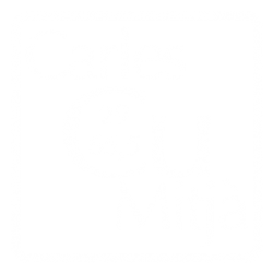
- Prepare a digital step wedge divided in 10% increments, or the sequence do you prefer, and print it with the same printer settings as for the positive. A model with eleven steps and a continuous ramp is shown in the Fig., 1. You can download here a printable version of Grayscale Color Mode, 8bit color depth and 360ppi of spatial resolution. Stouffer step wedges are well indicated if the positive transparency is on photographic film, as Stouffer is. This ensures a comparable transparency and behaviour to the UV light exposure. Nevertheless, translucent films like Pictorico or PermaJet used to print the positive transparency from digital image files have a quite different opacity relating to the photographic film. Beside that, if there is not available a densitometer, the Stouffer test marks are unusable, excepting by visual comparison. Dealing with digital images, I prefer to prepare the step wedge referred to pixel Gray Value (0 – 255) and Ink Coverage (100% – 0%) with exactly the same printer settings and ink I use to print the positive image transparency. I also use this 10Step test to include in the imaging plates to control at a glance the etching progress.
- Determine the minimum exposure time that produces an enough gelatin thick in the black. This can be done by incrementally exposing that test and then transferring the gelatin on a piece of glass. If a densitometer is not available, the result can be photographically reproduced and then the pixel grey value suitably measured as a consequence of the gelatin thickness presence in the different steps. A free software for any computer operative system that allows many kind of measurements and calculations over digital images is ImageJ.
- Determine, with the digitally prepared screen, the maximum etching time that avoids the open bite. This can be done by exposing a piece of carbon tissue through the screen with increments in time. Finally, the tissue is transferred to the copper plate with the usual method and the plate is etched in a, for instance, 40ºBé ferric chloride solution. The etching is stopped sequentially in time covering strips of the plate with packaging tape. Analysing the combined results with a magnifier and on the resulting print, is not so difficult to arrive to some conclusion about the approximate limits for the total etching time. The goal is an even and dense black without any signal of open bite caused by the lateral etching.
- Finally, with all those data, it is necessary repeat the trial with the complete exposure sequence, first to the screen and then to the positive transparency in order to fine tune the combined exposure times.
In my opinion, all that calibrating steps will provide a suitable exposure combination which will serve only as a starting point. The successive experience and most important, the characteristics of each image, will suggest some departures from this point of reference. Numbers, test targets and calibration graphs informs about the materials response but images are also a visual and perceptive experience. The fine tuning each image in a particular way, often can provide a much better visual and aesthetic result.
The step wedge shown in the Fig., 1 can be used both calibrating the system or to include it in the plate, above or beside the image. This helps to visually control de etching progress. When printed with the native resolution of 360ppi, it measures 105x30mm, little enough to avoid excessive copper discard and sufficient in size to control at a glance the etching changes in each ferric chloride dilution. After downloading it, check for the actual grey values of the steps. If there is some departure from the noted figures, check the clipping or colour settings (colour space, automatic ICC profiles, etc.) in the digital image processing software. The five steps at lower right corner are of respectively 100%, 75%, 50%, 25% and 0%, from down to up.
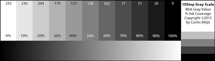
Some examples of calibrating process. As David Morrish recommends in his book (1), transferring the exposed gelatin on glass can help to better decide about the appropriate exposure time that provides a minimum thick of gelatin resist in black areas. In spite of the practical difficulties I have encountered to maintain the gelatin on the glass during the hot water wash, it is still possible to extract some conclusions from the example shown in the Fig., 2.
- Looking at the black extreme of the step wedge, at left with thinner gelatin resist, only the 8min exposure provides some separation between the respective 100% and 90% steps (take into account that this is an exposure without screen).
- The whites are better separated with 4min and barely separated in the 8min exposure step.
This probably suggest that the system admissible dynamic range is shorter than the dynamic range of the step wedge. Those data relates only to a given printer, ink and positive transparency printing media. If we don’t want or cannot change that, a possible solution is to digitally apply a dynamic range reduction to the step wedge image file. Reducing the equivalent to 1step (10%) would allow to expose for 5 or 6min with a fine separation both in highlights and shadows.

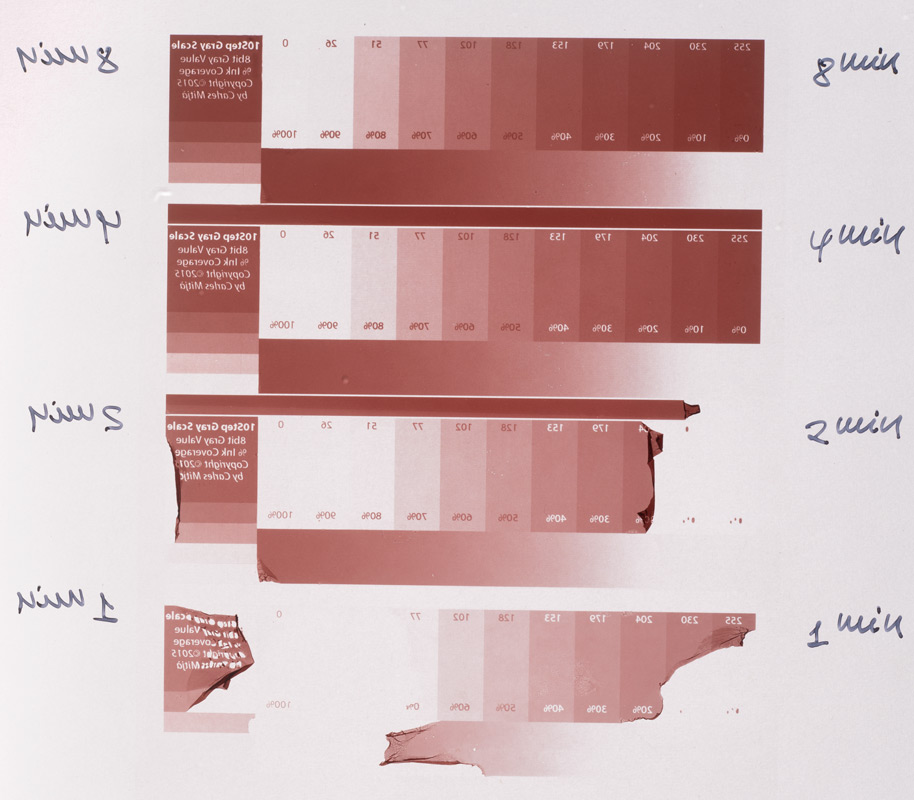
Fig., 3 shows a print obtained from a sequentially exposed step wedge. The step wedge image file was processed in order to reduce its dynamic range the equivalent to 1step (10%) as discussed above. The exposure sequence is, from down to up, 4min, 6min, 8min and 10min. The digital screen was previously exposed for 6min, the correct time found to allow for a dense black. The Fig., 4 shows a graph with two plots corresponding respectively to the 4min and 6min step wedges in the Fig., 3. Over each plot and with the same colour, simple linear regressions have been also calculated in order to help in the interpretation. While the 4min exposure allows for a better separation in the highlights, the 6min plot shows a slightly better separation in the shadows area and a greater slope that indicates a higher image contrast. In this case, the separation is better equaly spaced between the overall steps. Although this is not shown by the plots, it is important to realize that the 6min exposure will provide also the thickest gelatin resist which in turn, will need changes in the etching sequence to penetrate a given (or desired) depth in the copper plate. Up to the extend of my knowledge and from my reduced experience, we cannot qualify anyone of worse or better result. We can advantageously consider that for images that need a higher contrast and/or a better separation in the shadows, 6min would be the chose. Conversely, those images with no large shadow areas, with critical highlights and/or limiting contrast, would be better processed with 4min of exposure time. In between, we have still several possible exposure times around the 5min, that will provide intermediate results. Then, the control of the image tone and contrast is the result of suitably combine digital image processing, transparency exposure and etching sequence.
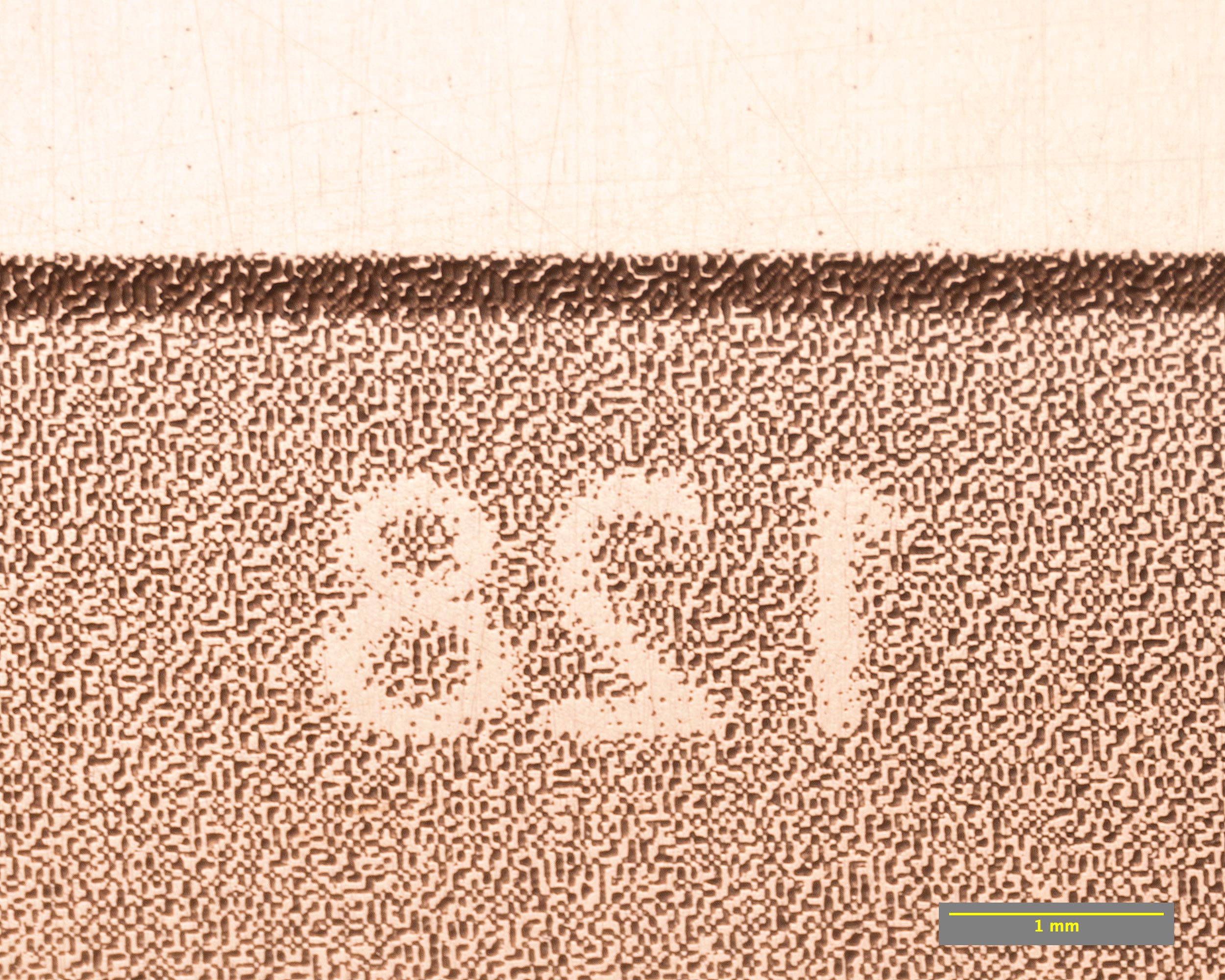
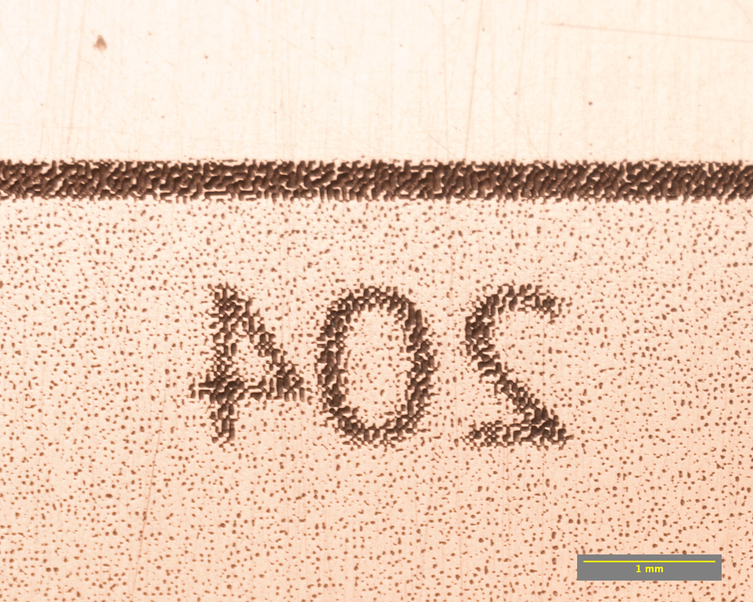
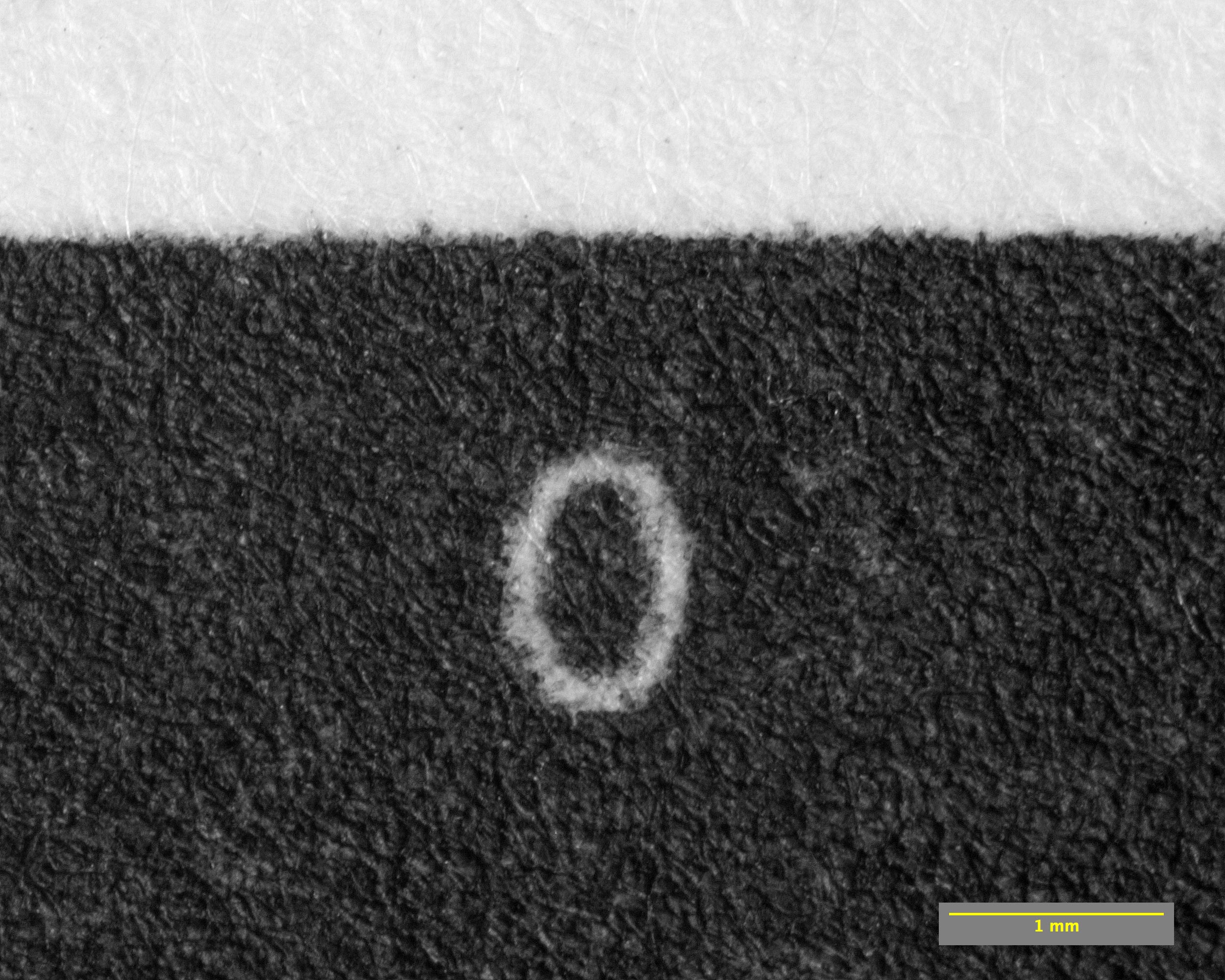
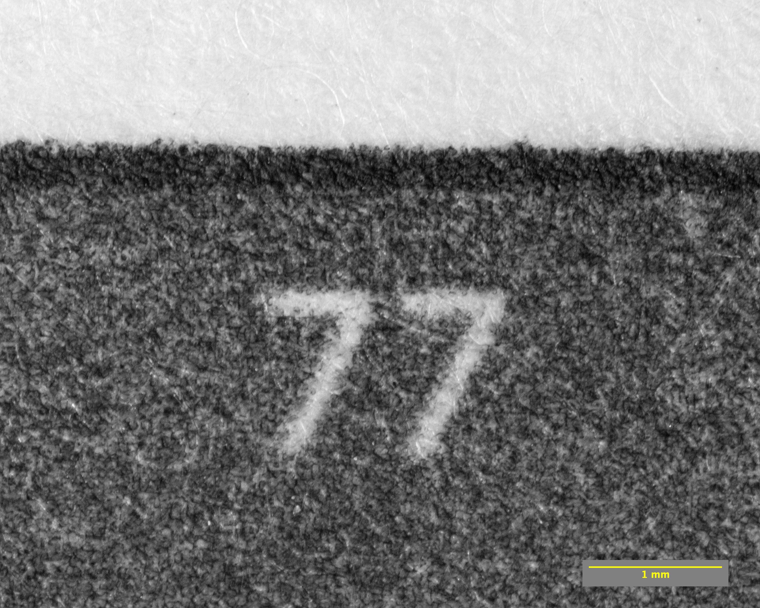
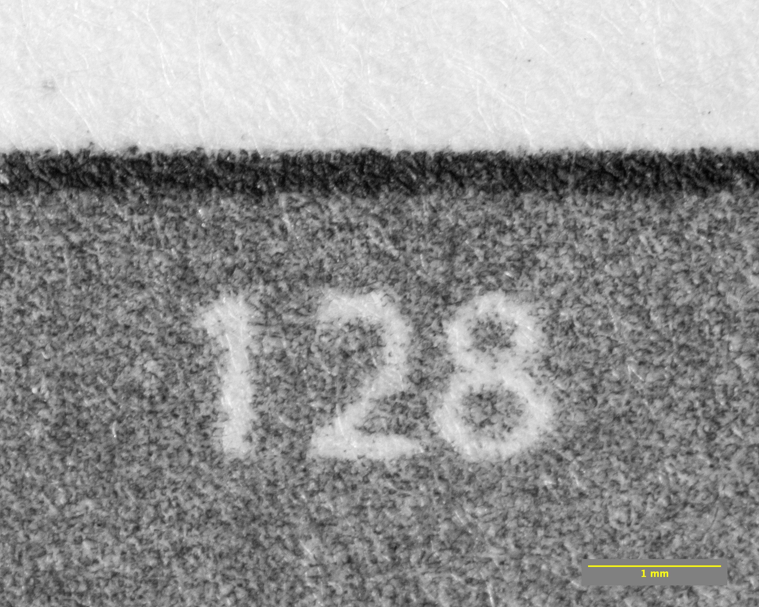
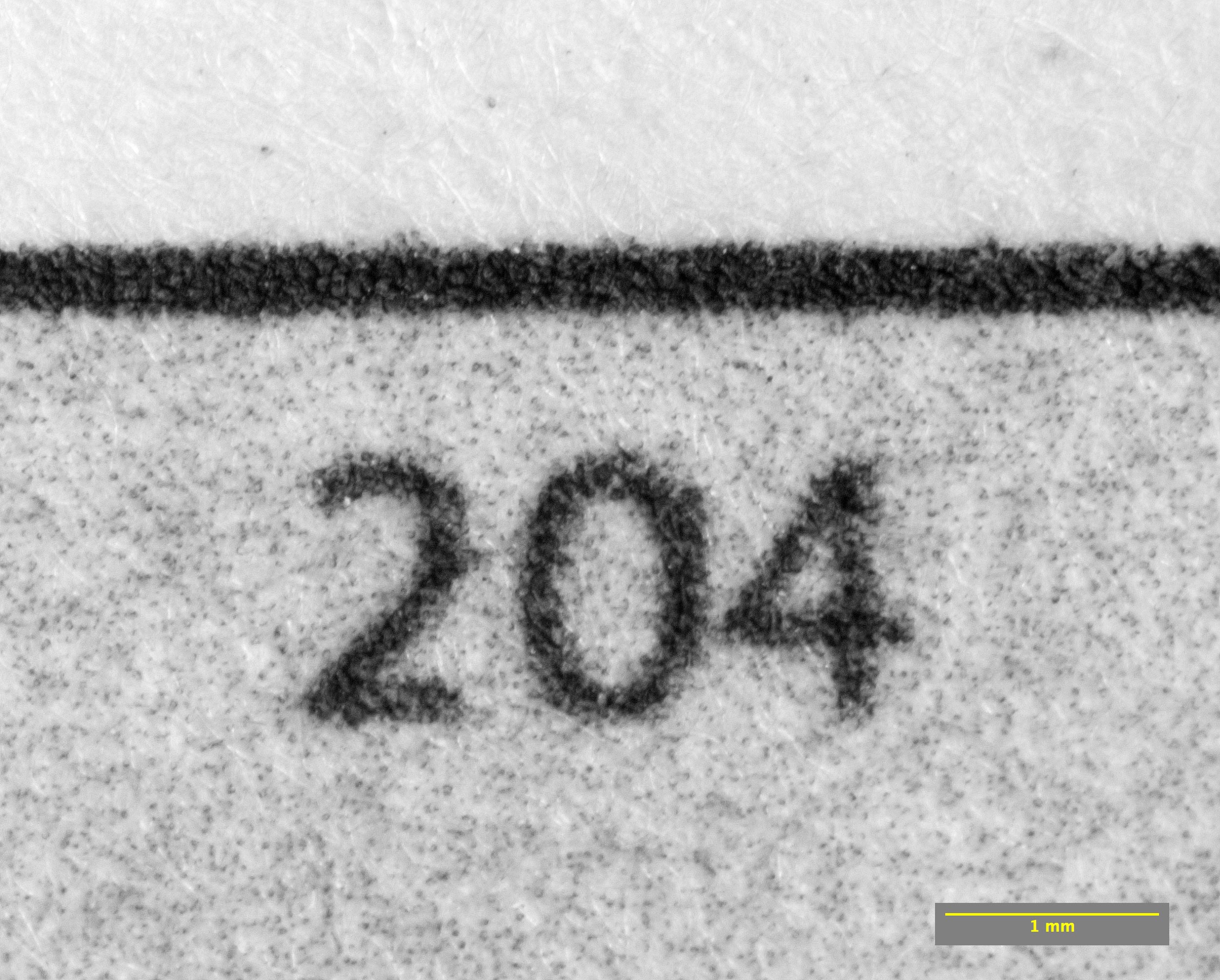
Screen Scheme and Etching. In order to better look at the kernel of the method, that is the sequential etching, I have taken the following photomacrographs from small areas of a plate (Table 1, upper row) and its corresponding print (Table 1, bottom row). The image on the plate is the same step wedge with 6min of exposure previously studied. There are shown only five equally spaced steps corresponding, from left to right, at 0, 77, 128, 204 and 255 grey values. Clicking on the pictures, will access to an enlarged view. It is very useful to compare each couple, plate and print, of the same grey value.
 |
 |
 |
 |
 |
 |
 |
 |
 |
 |
Table 1. Click on the images to access to enlarged view. Depending on the viewing display pixel size, the magnification will vary. In any case, the graphic scale at bottom right gives a guide about the actual magnification in each display.
As can be seen magnifying the previous images, although in the plate pictures it is clearly visible the screen structure, in the print magnifications it is almost disappeared after the ink is merged with the paper fibers. This means that the screen scheme aspect is not so important because it disappears under the pressure of the press roller. Some amount of ink is forced to enter in the paper fiber while other is spread over the surface, all that depending on the amount of ink present in the corresponding step. This ink amount is related with the etching depth. Finally, looking at the black (0) step, it is obvious that although there are present recessed areas caused by the lateral etching, they aren’t deep enough to provoke open bite. Perhaps this example shows an endpoint before the open bite appears.

As a final test, some average samples of pixel grey value have been taken from the print pictures of the previous series. This average results have been plotted in a graph that is shown in the Fig., 5. As can be observed in this case, the positive transparency exposure time, the etching sequence, the inking, the plate wiping and the etching press action have resulted in a quasi linear sequence, as is expected. Exaggerated departures of this linear behaviour, will show the effects of causes related with all those method steps.
References
1. MORRISH, D. and MacCALLUM, Marlene (2003) Copper Plate Photogravure, Demystifying the Process. Ed. Focal Press, Burlington MA.

One Reply to “”