

Un homenaje al trabajo de Charles Wheatstone y William Henry Fox Talbot
A tribute to the work of Charles Wheatstone and William Henry Fox Talbot
1. Introducción – El 21 de Junio de 1838, Charles Wheatstone presentó su trabajo “Contributions to the Physiology of Vision. Part the First. On some remarkable, and hitherto unobserved, Phenomena of Binocular Vision” (9-WHEAT) ante la Royal Sociaety, sobre los principios de la observación de la tercera dimensión a partir de dibujos bidimensionales. Poco tiempo después, en 1839 y 1840, fueron presentados los primeros procedimientos fotográficos razonablemente estables, el Daguerrotipo de Louis-Jacques Mandé Daguerre y el Calotipo de William Henry Fox Talbot. Desde un pimer momento Charles Wheatstone estuvo muy interesado en las nuevas técnicas fotográficas con el fin de obtener imágenes estereoscópicas que permitieran al observador ir un paso más allá que la simple representación bidimensional (10-WHEAT) and (11-WHEAT). Con el trabajo posterior de John Brewster y otros, la fotografía estereoscópica experimentó un éxito inmediato, siendo una de las aplicaciones más utilizada de la recién aparecida técnica fotográfica (3-METH).
En paralelo con ésta y otras aplicaciones, otro campo de investigación y gran desarrollo de las nuevas técnicas se centró en los procedimientos que ofrecían una mejor expectativa de permanencia de las imágenes fotográficas. Además de los cambios propuestos por nuevos procesos y algunos avances en la eliminación de residuos químicos en las fases de lavado, el trabajo de Talbot en fotograbado fue, con la tecnología disponible en el momento, una de las contribuciones más decisivas a la permanencia de las imágenes fotográficas. En su patente Nº565, titulada Improvements in the Art of Engraving y registrada en 1852, se describe el procedimiento para trasladar la información pictórica de una fotografía a una plancha de metal grabada con ácido. El texto introductorio dice: “The patent consisted of producing a photographic image on a metal plate, using this image as a resist to control the etching of that plate, and then printing the resulting plate using a conventional printing press and standard printer’s ink” (8-SHAAF).
Dependiendo de la tinta y el papel empleados, la expectativa de permanencia de las imágenes impresas debería ser al menos tan larga como la de los grabados tradicionales impresos en siglos anteriores. La imagen fotográfica sobre la plancha de metal se obtenía exponiendo al Sol una capa de gelatina bicromatada a través de un calotipo positivo, previamente encerado para transparentarlo en cierta medida. La plancha era de acero y el grabado se efectuaba mediante una solución de Cloruro de Platino.
Talbot introdujo diversas y progresivas mejoras al proceso, inicialmente denominado grabado fotográfico. Una de las más importantes fue el uso de una pieza de tejido durante la exposición para provocar el tramado de la imagen. Este tramado permitía una retención de tinta mejor en las áreas extensas de sombra durante la fase de limpieza de la plancha después del entintado. Talbot denominó a estas piezas de tejido como tramas fotográficas o velos.
En 1858 registró una segunda patente, la Nº875, con el mismo título que la anterior (8-SHAAF). Aún así, en esta ocasión cambió el nombre de las estampas resultantes por el de grabados fotoglíficos. Adicionalmente, adoptó el uso de una aguatinta de polvo de resina en substitución de la pieza de tejido para tramar la imagen, plancha de cobre y Cloruro de Hierro(III) como mordiente. Este sistema es el estadio de desarrollo más alto que Talbot consiguió aunque el método todavía adolecía de dificultades para preservar una gama tonal completa en relación al calotipo positivo, sobre todo en las sombras y los tonos medios. Fue en 1879, dos años después de la muerte de Talbot, cuando Karel Klic introdujo las modificaciones definitivas al método, tomando la idea del soporte temporal para la gelatina bicromatada establecido por Louis de Poitevoin para la técnica del Carbón Transportado y que fue desarrollada posteriormente por Joseph Swan. Klic no patentó el método pero le llamó fotograbado y rápidamente se acuño el término Método de Talbot-Klic (https://youtu.be/jozS7qKb7Co).
Pero existe otra relación entre los avances en fotografía estereoscópica anteriormente mencionados y el fotograbdo. De la relación epistolar entre Talbot y Wheatstone, basada en intereses comunes en diversos campos como el electromagnetismo y las máquinas eléctricas, puede deducirse que ya en 1840 Wheatstone experimentó con su estereoscopio de espejos con imágenes tomadas por Talbot (10-WHEAT). Más tarde, en 1858, hay una oferta escrita por Wheatstone para proporcionarle a Talbot imágenes en placa de vidrio para que pueda experimentar con su técnica del fotograbado. En el mismo 1858 y siguiendo con esta relación epistolar, Wheatstone escribe a Talbot: “… I think one of the most immediately profitable applications of your new art <*> would be to the production of stereoscopic pictures, for which there exists now an immense sale. Upwards of 3000 glass slides for the small stereoscopes have been published in Paris which are sold at prices varying from 8s/ to 12s/ each; even these pictures, already existing prod reproduced by your art they might be sold at 6s/ per dozen each, and would, I have no doubt meet with a considerable sale. There would be no expense beyond the transfer of the pictures and printing of the plates. My large stereoscope, far superior as it is to the others, has never become popular on account of the expense of the pictures. Were they reproduced by your method, I have no doubt that if some optician <sic> to take it up he would find it to answer his purpose.” (12-WHEAT) (<*> Wheatstone se refiere aquí al método de fotograbado de Talbot).
No existe ninguna evidencia documental de que Talbot respondiera a esta propuesta de Wheatstone. Hasta hoy tampoco se ha encontrado ningún fotograbado de un par estereoscópico entre la parte catalogada del extenso trabajo de Talbot. La respuesta sobre este asunto del profesor Larry J. Schaaf, Director del William Henry Fox Talbot Catalogue Raisonné, de la Universidad de Oxford, fue: “… all the known correspondence between Wheatstone and Talbot is posted. I know of no notes where he attempted to use both halves of any stereo, apparently this did not interest him. There is a very large number of uncatalogued and largely unexamined photogravures, so finding a pair is not impossible.”
Hoy podemos imaginar esta relación epistolar entre Wheatstone y Talbot como la huella de un camino a seguir. Basándose en ello, el trabajo XIX·XXI presenta la edición de tres heliograbados (fotograbados en plancha de cobre) de imágenes estereoscópicas. Para ello, se han tomado fósiles de Ammonoidea, Echinoidea y Gastropoda como sujetos, siendo éstos a su vez huellas de un pasado común. En la fase final del trabajo, la huella de la plancha de cobre sobre el papel no pretende ser un final del camino, sino una huella más que contribuya a cerrar este círculo de complicidades entre estereoscopía y fotograbado. Este trabajo también quiere ser un modesto homenaje al trabajo desarrollado por estos pioneros de ambas técnicas.
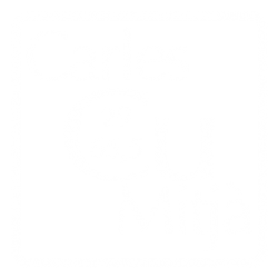
2. Captación de las Imágenes – De las diversas opciones disponibles en fotografía estereoscópica y con el fin de trabajar con el nivel de desarrollo técnico existente en los tiempos de Wheatstone y Talbot, se ha decido utilizar la llamada estereoscopía de imágenes en paralelo. En este método, el par de imágenes necesarias de cada sujeto, tomadas secuencialmente con un desplazamiento lateral del punto de vista (Fig., 1), se muestran a los respectivos ojos izquierdo y derecho del observador. Con el fin de aislar la imagen asignada a cada ojo, se utiliza un aparato denominado estereoscopio.
La Fig., 1 muestra el desplazamiento lateral aplicado a la cámara para tomar las respectivas imágenes izquierda y derecha. Esta separación, llamada base estereoscópica, puede tener diversa medidas según la proximidad o alejamiento de la cámara respecto del sujeto fotografiado. La cifra de 60mm utilizada en este caso se razonará más adelante. Nótese en el ejemplo que los respectivos lados l y r del sujeto O son sólo visibles para una de las dos posiciones de cámara, L o R. Esta disparidad de las partes visibles u ocultas del sujeto entre las dos imágenes, permite a la visión del observador detectar la tercera dimensión o profundidad cuando el par de imágenes se observa a través de un estereoscopio. Se percibe así la tercera dimensión a partir de dos imágenes bidimensionales. De este esquema también se deduce que con el fin de alcanzar el efecto deseado, este desplazamiento lateral ha de ser, en la medida de lo posible, la única diferencia entre ambas imágenes.
1. Introduction – On June the 21th of 1838, Charles Wheatstone presented his paper “Contributions to the Physiology of Vision. Part the First. On some remarkable, and hitherto unobserved, Phenomena of Binocular Vision” (9-WHEAT) on the Royal Society, about the priciples of observing the third dimension from bidimensional drawings. Short time later, on 1839 and 1840, the first reasonably stable photographic procedures were also presented, the Daguerreotype from Louis-Jacques Mandé Daguerre and the Calotype of William Henry Fox Talbot. From the very early time, Charles Wheatstone was deeply interested on the new photographic techniques in order to obtain stereoscopic images, allowing the observer to go a bit beyond the bidimensional representation (10-WHEAT) and (11-WHEAT). Because of the work from John Brewster and others, the stereoscopic photography experimented an almost immediate success, being one of most employed applications of the new photographic techniques (3-METH).
In parallel to those and other applications, a field of research and growing of these new techniques was focused on the procedures to offer a better life expectancy of the photographic imaging. Beside the changes proposed by new processes and some advances in chemical residues elimination, wich caused the degradation of the on paper pictures, the work of Talbot on photogravure was, with the technology available at this time, one of the best contributions at this photography life expectancy. In his patent Nº565, entitled Improvements in the Art of Engraving and registered by Talbot on 1852, it is described the procedure to translate the pictorial information of a positive photographic material onto a metal plate etched by acid. The introductory text said: “The patent consisted of producing a photographic image on a metal plate, using this image as a resist to control the etching of that plate, and then printing the resulting plate using a conventional printing press and standard printer’s ink” (8-SHAAF).
Depending on the ink and paper employed, the life expectancy of the printed pictures would be at least as long as the traditional gravures printed on the past centuries. The photographic image over the plate was obtained exposing under the Sun light a layer of bichromated gelatin through a positive calotype paper, being previously waxed to transparent it to some extend. The plate was of steel and the etching performed by a solution of Platine Chloride.
Talbot introduced diverse and progressive improvements to the process, initially called photographic engraving. One of most important was the use of a piece of textile fabric during the exposure in order to screening the image. This screening allowed for a better ink retention in the shadow extended areas during the plate wiping. Talbot named those rag pieces as photographic screens or veils.
On 1858 he registered a second patent, the Nº875 with the same title Improvements in the Art of Engraving (8-SHAAF). Nevertheless, in this case he changed the name of the resulting print as photoglyphic engraving. Additionally, adopted the use of resin powder aquatint in substitution of the fabric screen, copperplate and Ferric Chloride (III) as etching solution. This system was the higher state of development achieved by Talbot while it still encompassed a certain difficult to preserve a complete tonal range in the final print, mainly in the shadows and mid tones. It was on 1879, two years later Talbot passed away, when Karel Klic introduced a definitive method modification taking the idea of a temporal gelatin support stated by Louis de Poitevoin for the Carbon Transfer technique, which was later developed by Joseph Swan. He named the process as photogravure and quickly was called as Talbot-Klic method (https://youtu.be/jozS7qKb7Co).
But there is also another link between the advances early mentioned of the stereoscopy and photogravure. From the epistolary relationship between Talbot and Wheatstone, based in common interests as electromagnetism and electric machines, it can be derived that on 1840 Wheatstone experimented with his stereoscope using glass plates of images taken by Talbot (10-WHEAT). Later on 1858, there is an offer from Wheatstone to provide Talbot with glass plates helping him in his experiments on photogravure. Following with this relationship between stereoscopy and photogravure, on the same 1858, Wheatstone wrote to Talbot: “… I think one of the most immediately profitable applications of your new art <*> would be to the production of stereoscopic pictures, for which there exists now an immense sale. Upwards of 3000 glass slides for the small stereoscopes have been published in Paris which are sold at prices varying from 8s/ to 12s/ each; even these pictures, already existing prod reproduced by your art they might be sold at 6s/ per dozen each, and would, I have no doubt meet with a considerable sale. There would be no expense beyond the transfer of the pictures and printing of the plates. My large stereoscope, far superior as it is to the others, has never become popular on account of the expense of the pictures. Were they reproduced by your method, I have no doubt that if some optician <sic> to take it up he would find it to answer his purpose.” (12-WHEAT) (<*> Wheatstone is refering here to the Talbot’s Photogravure method).
There is no evidence about an answer from Talbot to this proposal. Until today, neither has been found any photogravure of an stereoscopic pair among the catalogued part of the extensive work of Talbot. The answer to a question proposed to the professor Larry J. Schaaf, Director of the William Henry Fox Talbot Catalogue Raisonné, from the Oxford University, about this matter, was: “… all the known correspondence between Wheatstone and Talbot is posted. I know of no notes where he attempted to use both halves of any stereo, apparently this did not interest him. There is a very large number of uncatalogued and largely unexamined photogravures, so finding a pair is not impossible.”
We can today imagine this epistolary relationship between Wheatstone and Talbot as the footprint of a path to follow. Relying on that, the XIX·XXI project features the edition of three heliogravures (photogravure on copperplate) of stereoscopic images. Fossils of Ammonoidea, Echinoidea and Gastropoda have been taken as a photographic subjects, being in turn the footprint of a common past. In the final step of the project, the footprint of the copperplate on the paper don’t dare to represent the end of the path, but only one more of the footprints contributing to close the circle of complicities between stereoscopy and photogravure. Also serve this work as a simple tribute to the work developed by those pioneers of the respective techniques.
2. Image Capture – From the several options available and with the goal to work at the same technical level existing at the Wheatstone and Talbot time, the so called side by side stereoscopy it’s been chosen. In this method, the two necessary images of each subject, taken sequentially with a lateral displacement of the point of view (Fig., 1), are shown to the correspondent left and right observer eyes. In order to isolate the image assigned to each eye, an instrument called stereoscope is used.
The Fig., 1 shows the lateral displacement applied to the camera for the respective left and right pictures. This separation, called stereoscopic basis, can take diverse magnitudes depending on the distance from the camera where the subject is placed. The figure of 60mm used in this case will be further reasoned. Note as in the example the respective sides l and r of the subject O are uniquely visible for one of the camera positions, L or R. This disparity of the hidden or visible parts of the subject, allows to the observer vision to detect the third dimension when the pair of images is seen through an stereoscope. The third dimension is then perceived from a couple of bidimensional pictures. From this scheme can be also derived that in order to achieve the desired effect, this lateral displacement must be, as far as possible, the only difference between the pictures of the stereoscopic pair.
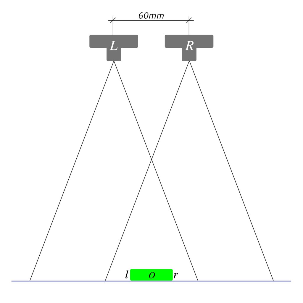
Con el fin de reducir al mínimo los errores de posición entre el sujeto, la cámara y las respectivas imágenes izquierda y derecha, el dispositivo de captación empleado incorpora una serie de características que se describen en los párrafos siguientes. El cuerpo de cámara empleado es un Sony Alpha 7II provisto de un objetivo Nikon Micro Nikkor 55mm f/3.5. Como el punto de vista es cenital, la cámara se ha fijado a un estativo de reproducción que asegura el paralelismo de los planos respectivos de sensor y soporte del sujeto fotografiado. El sistema de sujección permite movimientos micrométricos a lo largo del eje vertical, mientras que los desplazamientos laterales se realizan por simple liberación de la mordaza de sujección de tipo Arca Swiss (Fig., 2).
In order to reduce to the minimum the position errors between the subject, the camera and the respective left and right pictures, the capture setting employed has a series of properties being described in the next paragraphs. The camera body is a SONY Alpha7II provided by a Nikon Micro Nikkor 55mm f/3.5 lens. Being zenith the chosen point of view, the camera is attached to a reproduction column that ensures a parallelism between the respective planes of camera sensor and subject support. The mounting system allows for micrometrical displacements along a vertical axis, while the lateral displacement is achieved by simple liberation of the Arca Swiss type clamp (Fig., 2).
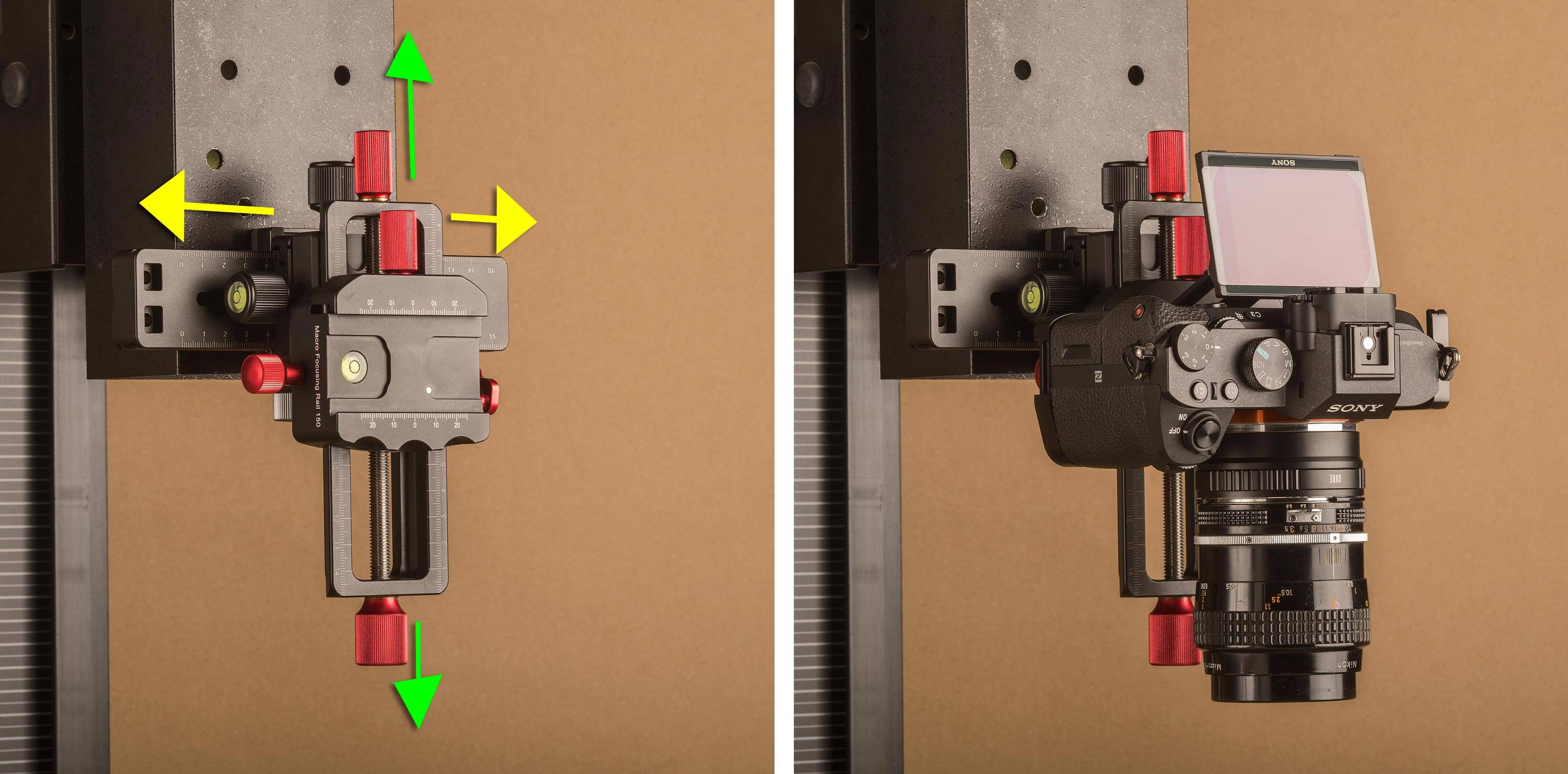
Figure 2 – At left, assembly of vertical and horizontal sliders. At right, the camera attached to the assembly.
Todos los desplazamientos disponibles aseguran que se mantenga el paralelismo entre los planos mencionados anteriormente. El desplazamiento vertical micrométrico facilita el enfoque de objetos de diverso tamaño y grosor manteniendo el aumento lateral predeterminado por la posición del anillo de enfoque del objetivo. El desplazamiento lateral aporta la base estereoscópica necesaria. El conjunto cámara-objetivo se puede desplazar también verticalmente mediante los mecanismos de la columna de reproducción.
Los tres fósiles escogidos para este trabajo tiene tamaños distintos. Por lo tanto, si se quiere mantener la misma relación sujeto-fondo en la imágenes finales, sería necesario cambiar la distancia cámara-sujeto para cada caso y ello provocaría a su vez cambios en el aumento lateral, en la profundidad de campo y en la perspectiva de observación del observador final. Además, dado el tamaño de alguno de los fósiles, también sería necesario reducir esta distancia cámara-sujeto más allá de la distancia mínima de visión confortable del sistema de visión humano, que es de aproximadamente 350mm.
Esta distancia, determinada por la capacidad de enfoque del Sistema Visual, genera la perspectiva de visión más cercana al sujeto que un humano puede tener a ojo desnudo sin ayuda óptica externa. Desde el punto de vista de un observador con visión sana o convenientemente corregida, tanto la forma de los objetos como la relación entre sus dimensiones serán siempre percibidas como consecuencia de esta distancia. Cualquier acercamiento a una distancia de observación menor implica el uso de ayuda óptica externa y ello cambia a su vez la perspectiva de observación. De ello se derivan a la vez al menos dos cuestiones más:
– Incluso modificando la base estereoscópica para una distancia de observación menor que la citada, no existe un acuerdo entre diversos autores sobre la experiencia perceptiva que los observadores pueden tener para una imagen que ha sido tomada a una distancia a la cual ellos no habrían podido observar el objeto en la realidad.
– El Sistema Visual observa a una distancia de 350mm o más aquellos objetos lo suficientemente grandes como para no requerir el uso de sistemas ópticos de aumento.
Dado que los tres fósiles escogidos no muestran ninguna dificultad para ser observados a la citad distancia sin necesidad de ayuda óptica externa, las imágenes se han tomado a una distancia similar, lo que contribuye a proporcionar una perspectiva muy cercana a la de la visión estándar. La distancia real de toma se ha aumentado hasta los 400mm para disponer de algo más de espacio para la iluminación de la escena. Esta distancia de toma implica el uso de una base estereoscópica de 65mm, promedio de separación de los ojos. Aún así, esta separación no toma en cuenta la convergencia de los globos oculares cuando se observa a distancias tan cortas. Dicha convergencia se puede simular mediante la rotación de los ejes ópticos del objetivo d ela cámara en las respectivas tomas L y R, pero ello introduce una distorsión geométrica en las imágenes captadas que debe ser corregida posteriormente mediante procesado de imagen. Para evitar este inconveniente, un procedimiento común en estos casos consiste en reducir la base estereoscópica al tiempo que se mantiene el paralelismo entre los ejes ópticos de ambas tomas (1-LIN). En el presente caso, la base estereoscópica se ha reducido a 60mm. Con estos parámetros ya fijados, se han realizado algunos cálculos para asegurar que la profundidad de campo disponible es suficiente para el grosor de los fósiles fotografiados:
– Con un objetivo de 55mm de longitud focal y una distancia objeto de 400mm, la distancia imagen es de 57,14mm.
– El cociente entre las respectivas distancias imagen y objeto da una aumento lateral de m = 0,14 para esta situación.
– Dado que con el sensor de la cámara empleada el límite por difracción se sitúa en f/16, se calcula la profundidad de campo disponible con este diafragma. El resultado es de PdC = 63,8mm (4-MIT). El grosor de los tres fósiles no excede esta cifra en ninguno de ellos, por lo que no es necesario en este caso aplicar técicas de apilamiento de imágenes o focus stacking.
Una última verificación debe asegurarnos que después del recorte necesario en cada caso para ajustar la relación sujeto-fondo, queda todavía un número de pixeles suficiente para el tamaño y la resolución de impresión necesarios. Esto es especialmente importante en el caso del fósil de menor tamaño, que solicita el recorte mayor. En este trabajo, se ha previsto que los pares estereoscópicos se observen mediante el estereoscopio OWL de la London Stereoscopic Company (Fig., 3) (2-LON). Con una separación de puntos homólogos recomendada de 70mm, las imágenes delpar estereoscópico deben imprimirse a un tamaño de 70x70mm o menor.De este tamaño y de la resolución de salida necesaria (288ppi) resulta fácil calcular un número de píxeles mínimo necesario de 795x795pix para cada imagen. Como la imagen ya recortada del fósil de menor tamaño mide 2534x2534pix, no existe ninguna limitación al respecto. Los archivos de toma originales se conservan a su tamaño original para posible usos en otro ámbito y se generan versiones al número de píxeles necesarios para la impresión mediante re-muestreo.
All the available displacements ensure the parallelism between the above mentioned planes. The vertical micrometrical displacement provides the focusing of diverse size and thickness subjects both maintaining the lateral magnification provided by the lens helical focusing ring. The lateral displacement provides the necessary stereoscopic basis between the pictures of the pair. The ensemble camera/lens can also travel along a vertical axis through the mechanisms of the reproduction column.
The three fossils chosen for the project are different in size. Then, if the same relationship between figure and background want to be maintained in the final prints, it would be necessary to change the camera to subject distance for each of them and this would provoke in turn changes in lateral magnification, depth of field and perspective perception to the observer. Additionally and given the size of the fossils, it would be necessary for some of them to close up the camera to the subject at a distance shorter than the so called human comfortable vision distance, being of approximately 350mm.
This distance, determined by the focus on capabilities of the human vision system, generates a perception of perspective being the closer to an object that the naked eye can observe with sharpness and without external optical aid. From the point of view of an observer with healthy or suitably corrected vision, both the shape of the objects as the relationships of their own dimensions will be perceived as a consequence of this distance. Any close up position shorter than that needs of an external optical aid and this changes in turn the perspective of observation. From all that can be derived in turn two more questions at least:
– Even modifying the stereoscopic basis for a distance shorter than the above cited, there is not an agreement among several authors about how it will be the perceptive experience of the observers, looking at an image taken at a distance at which they cannot be able to observe in the real world.
– The Human Visual System observes at a distance of 350mm or more those objects big enough so not requiring the use of external magnification optics.
Given that the three fossils chosen for the project do not show any difficult to be observed by the naked eye at this distance of 350mm, the pictures have been taken at a similar distance, allowing in turn for a perception of perspective very close to the standard vision. The actual distance of the camera to the subject was of 400mm, slightly longer than the above cited, but providing a bit more space for the lighting setting up. This distance allows for a stereoscopic basis equal to the average separation of human eyes of about 65mm. With this stereoscopic basis it is not taken into account the human eye convergence. This convergence can be simulated by the camera rotating its axis accordingly for each one of the L or R pictures, but this in turn introduces in the pictures a Keystone effect which must be corrected later by digital image processing. A common intermediate procedure is to reduce a bit the stereoscopic basis but maintaining the parallelism between the respective sensor and subject planes (1-LIN). In this case, the stereoscopic basis has been reduced to 60mm. With those parameters already decided, some calculations had been done to control the depth of field available:
– With a lens of 55mm of focal length and an object distance of 400mm, the image distance is of 57.14mm.
– The quotient between the respective image and object distances, gives a lateral magnification of m = 0,14 for this situation.
– Provided that with the camera sensor employed the limit by diffraction is stated at f/16, the depth of field available for this diaphragm number is calculated. The result is DF=63.8mm (4-MIT). The fossils thickness does not exceed this value in any case. Then, the images can be taken with a single shot, avoiding the need to apply the focus stacking technique.
A last verification must ensure that after cropping the respective images to the desired subject to background relationship, there are still an enough number of available pixels for the printing needed size. This is specially necessary for the smaller fossil, demanding the biggest cropping by report to the original image. In this work, the stereoscopic pair it is foreseen to be observed through the OWL Stereoscope from the London Stereoscopic Company (Fig., 3) (2-LON). Being the recommended separation of homologue points for this stereoscope of 70mm, the images of the stereoscopic pair must be printed at a size of 70x70mm or less. From this size and the output resolution on the image to be sent to the print (288ppi), it is easy to calculate than the minimum number of pixels needed is of 795x795pix for each picture composing the stereoscopic pair. As the cropped picture of the smaller fossil still measures 2534x2534pix in size, there is not any constraint on this matter. Therefore, the three pictures have been taken with the above described camera set up. Finally, the original pictures will be preserved at its original size allowing for further applications. The files to be sent to the printer in order to generate the positive transparencies intended for heliogravure, will be downsampled from this original files to the necessary number of pixels.
3. Esquema de Iluminación – La aproximación estética de las imágenes de este trabajo, quisiera situarse amedio camino entre la mera descripción documental y la imagen pictórica. Aunque en los primeros tiempos de la Fotografía ésta tenía como objetivo primordial la mera documentación, pronto se adoptó el desarrollo de un lenguaje estético propio. En este trabajo y con el fin de describir las características más relevantes de los tres tipos de fósil, se ha escogido un punto de vista cenital para todos ellos. Este punto de vista está también relacionado con la observación habitual de este tipo de especímenes en las vitrinas de los museos o colecciones. Aún así y con el fin de evitar un exceso de asepsia en el resultado final, se ha añadido un fondo texturado de tipo mineral. Esta textura, más allá de su contribución estética, representa una continuidad con el material del cual los fósiles están compuestos.
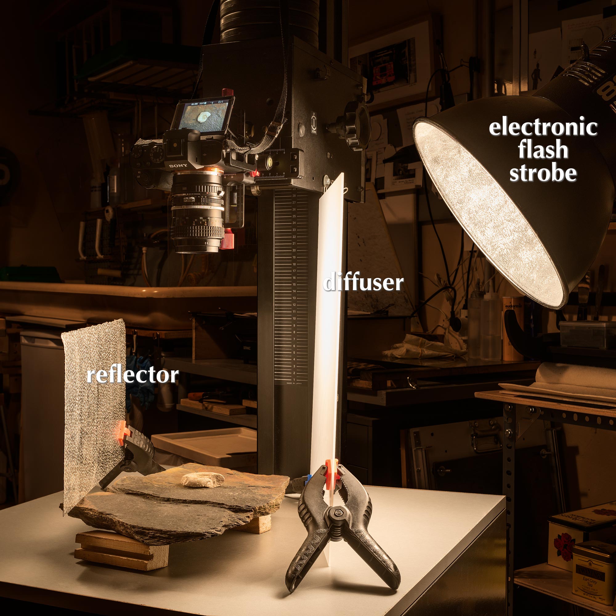
Para contribuir a una correcta descripción del volumen de los fósiles, se ha utilizado un esquema de luz difusa. Ello proporciona un borde de sombra suave y degradado. Esta suavidad evita una exceso de presencia de la sombra compitiendo con el propio objeto y no provoca conflictos con la textura del fondo en las zonas en sombra. La fuente de luz difusa es una pieza de plástico translúcido colocada relativamente cerca del sujeto. Su gran tamaño relativo con respecto al del sujeto asegura una buena uniformidad de la iluminación en el área de interés.
En la Fig., 4 se muestra el esquema de iluminación completo. Una antorcha de flash electrónico se ha emplazado detrás del difusor mencionado. La distancia del flash al difusor determina el grado de difusión sobre el sujeto y, como consecuencia, el grado de suavidad de la sombra proyectada por el mismo. La altura de la antorcha controla la visibilidad de la textura y la longitud de las sombras proyectadas. Finalmente, un reflector de aluminio corrugado se utiliza en el lado contrario al difusor para controlar el contraste de iluminación. La distancia del reflector al sujeto modula la visibilidad de la textura del fondo en las zonas en sombra. Para cualquier ratio de contraste deseado en la imagen final, el ratio de contraste de la iluminación debe mantenerse siempre algo por debajo. El procesado de imagen posterior proporcionará la oportunidad de elevar este contraste si así se desea, mientras que reducir un contraste excesivo no será siempre posible.
3. Lighting Scheme – The aesthetic approach for the pictures of this work, would be inscribed at a medium distance between the mere documentary description and the pictorial image. While at the very early times of Photography the mere reproduction goal was very common, a development of its own language was quickly adopted. In this work and in order to describe the relevant characteristics of the fossils, a zenith point of view is chosen. This point of view is also the most commonly employed to observe museum and/or collection specimens. Nevertheless, in order to avoid an excessive asepsis in the final result, a textured mineral background is added. This texture, beyond its complimentary aesthetic contribution, represents a continuity with the material from what the fossils are made.
Contributing to a correct description of the subjects volume, a diffuse lighting scheme is used. This allows for a smooth shadow borders. This smoothness avoids in turn an excessive prominence of the shadow competing with the subject itself and do not provokes a conflict with the background texture. The diffuse light source is a translucent plastic sheet positioned very close to the subject. Its relative size to the subject ensures the evenness of the general illumination.
In the Fig., 4, the complete lighting scheme is shown. An electronic flash strobe is placed behind the diffuser. The distance from this flash to the diffuser determines the light diffusion and, as a consequence, the shadow border projected by the subject. The height of the flash drives the visibility of the subject texture and the length of the projected shadows. Finally, a corrugated aluminium sheet acts as a light reflector controlling the lighting contrast. Its distance to the subject allows to control the persistence of texture in the shadow areas. For any desired contrast ratio in the final image, the lighting contrast ratio must be maintained always a bit below. The later digital image processing will provide the opportunity to rise this initial contrast, while to do conversely wouldn’t be always possible.
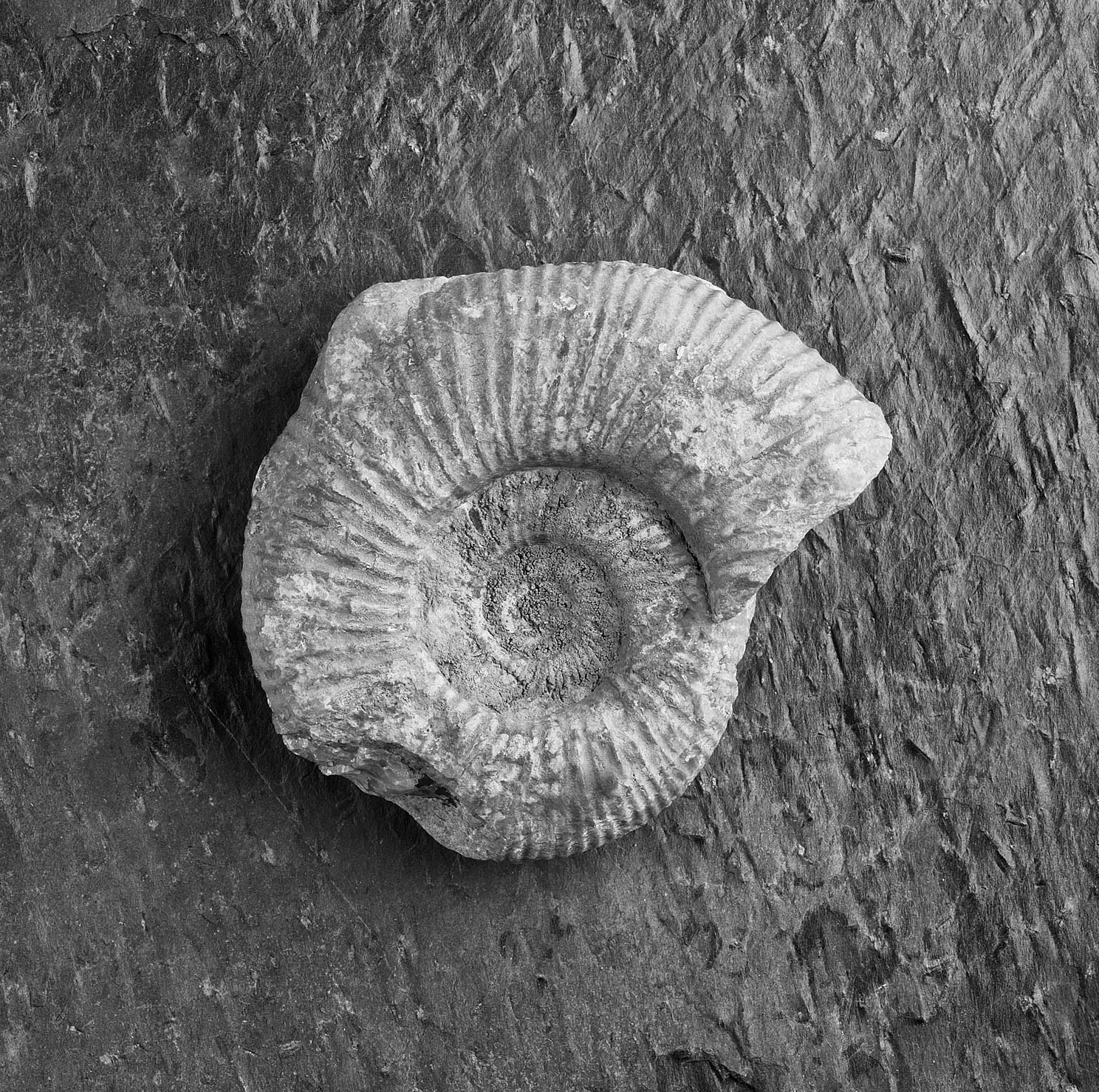
La Fig., 5 muestra la imagen izquierda del par estereoscópico del fósil de Ammonoidea. En ella pueden observarse la textura del fondo, la longitud de la sobra proyectada y la presencia de textura visible en las zonas en sombra. Dentro de ciertos límites físicos, estas características pueden modularse como se desee mediante las distancias y ángulos descritos anteriormente. Tomando imágenes destinadas a pares estereoscópicos a distancias relativamente cercanas al sujeto también pueden observarse diferencias de iluminación entre ambas imágenes. Esto está causado por el cambio entre los respectivos puntos de vista. Como regla general, estos cambios serán más evidentes cuanto más especulares sean las superficies de los objetos fotografiados. En este caso, mientras los fósiles no presentan cambios significativos entre las imágenes izquierda y derecha, estas diferencias están claramente presentes en los respectivos fondos (Fig., 6). Diferentes materiales presentan diferente especularidad. Aunque ello podría considerarse como un problema a la hora de captar este tipo de imágenes, la experiencia de observación a través del estereoscopio muestra como el cerebro se encarga de fusionar perfectamente ambas imágenes, soslayando dichas diferencias. De hecho, estas diferencias en tono y especularidad están también presentes para los respectivos ojos izquierdo y derecho en la observación directa a ojo desnudo. Por lo tanto, dichas diferencias no se ajustan en la fase de post-producción y el procesado de la imagen se realiza para el conjunto del par estereoscópico.
The Fig., 5 shows the left image of the Ammonoidea stereoscopic pair. There can be observed the background texture, the shadow length and the presence of texture into the areas in shadow. In between some physical limits, those parameters can be modulated as desired by means of the above described distances and angles. Taking images for stereoscopic pairs at a relative close up distance, there can be observed some lighting changes between the couple of images. This is caused by the different point of view used on each respective image. As a general rule, those differences will be more evident as higher is the specularity of the subject materials. In this case, while the fossils do not show relevant differences, they are fairly present in the background (Fig., 6). Different materials have diverse specularity. While it could be supposed as a constraint, the observation of the stereoscopic pair through the stereoscope shows as those differences are perfectly fused by the brain of the observer. In fact, these differences in tone and specularity are also present for the respective left and right eye in a naked eye observation. Therefore, those changes in tone aren’t fixed in the post-production. Both the raw files and the final files processing is performed for the whole stereo pair.
4. Procesado de las Imágenes – La secuencia del procesado digital de las imágenes se ha realizado como sigue:
– Los archivos RAW tomados por cámara se ha procesado mediante el programario Adobe Camera Raw aplicando unos ajustes previamente determinados para imágenes tomadas con esta combinación de cámara y objetivo (7-MIT).
– Una vez procesados, las imágenes se han guardado como archivos .psd codificados respectivamente como L y R.
– Ambos archivos L y R se han abierto en Adobe Photoshop como capas de un mismo archivo de imagen. Una Capa Fondo se ha añadido al archivo.
– Las capas L y R se alinean con respecto a una zona cercana al centro del fósil. Aplicar el Modo de Fusión Diferencia a la capa superior facilita esta operación de centrado.
– La imagen se recorta a la proporción 1:1 y hasta donde se considera correcto en términos de relación sujeto-fondo. La opción Borrar los Píxeles Recortados evita conflictos posteriores en el manejo de las capas.
– Se ajusta ahora la anchura del Lienzo a un tamaño 2P, siendo P el número de píxeles de uno de los lados de la imagen resultantes del recorte anterior.
– Se añade un número de píxeles suficiente para disponer de una barra de separación central entre ambas imágenes del par. Este número se deduce del espacio necesario y de la resolución de salida para la impresión del fotolito positivo destinado al heliograbado.
– Las respectivas capas L y R se desplazan ahora a los correspondientes extremos del Lienzo.
– Se toma una selección aproximada y difuminada de ambos fósiles, se codifica y se guarda.
– Tomando dicha selección y su inversa, se generan Capas de Ajuste de Curvas y de Conversión a BN. Estas capas se utilizan para la conversión a blanco y negro y para ajustar el contraste final deseado tanto en el fósil como en el fondo. Si persiste algún resto de color en los bordes difuminados de las Máscaras de Capa, se aplica una Capa de Ajuste de Tono-Saturación para desaturar este remanente de color.
– Se genera una Capa Resumen del conjunto ajustado y se aplica en ella la mejora de visibilidad de bordes necesaria.
– Una segunda Capa Resumen en la parte superior de la Paleta Capas servirá para clonar o eliminar los pequeños defectos que puedan detectarse como diferencias entre ambas imágenes del par estereoscópico.
– Después de guardar los cambios, se guarda una versión TIFF sin capas i 16bit.
– Se re-muestrea este archivo TIFF al tamaño en píxeles necesario para la correcta impresión del fotolito positivo para heliograbado. El tamaño de impresión debe respetar la separación de 70mm entre puntos homólogos solicitada por el estereoscopio OWL de la London Stereoscopic Company. Se reduce a continuación la profundidad de color a 8bit.
– La imagen se invierte ahora lateralmente y se inserta en una plantilla para fotolitos de heliograbado comola que se muestra en la Fig., 7.
La plantilla para heliograbado incorpora a la derecha una escala de grises de once pasos. Ésta se utiliza para controlar la progresión de la mordida de la plancha con el baño de Cloruro de Hierro (III). Una vez finalizada la espación del heliograbado, esta escala de grises sirve también para comprobar la linealidad del resultado en densidad i el valor de densidad obtenido en el escalón negro con Valor de Gris 0 o 100% de tinta. Esta densidad debería acercarse a la máxima que es capaz de proporcionar la tinta empleada.
4. Digital Image Processing – The digital image processing sequence is as follows:
– The raw files have been processed in Adobe Camera Raw applying a previously prepared settings profile intended for pictures taken with this camera and lens (7-MIT).
– When processed, the images are saved as .psd files and coded as L or R.
– Both L and R files are opened as layers in a new image file. A white Background Layer is also created.
– The L and R layers are aligned by reference to a common subject property in the center of the picture. Applying the Difference Mode to the upper layer helps in this alignment.
– The image file is then cropped to a 1:1 size ratio with the option Delete Cropped Pixels activated. This cropping determines the subject to background relationship.
– The Canvas Width is adjusted to a 2xP size, where P equals the number of image side pixels resulting from the former cropping.
– A number of pixels is added to the image canvas providing the separation needed at the center of the stereoscopic pair. This number is derived of the needed space and the output resolution for the printed positive transparency intended for heliogravure.
– The layers L and R are respectively positioned at the extremes of the image canvas.
– A rough selection of both fossiles is coded and saved.
– Taking this saved selection and its inverse, Adjustment Layers of BW Conversion and Curves are created on top. These layers allow for the adjustment of the BW conversion and general contrast in a separate way for the fossil or the background. The layer masks are smoothed to avoid artefacts. If there is some remaining of the original color in the borders of the layer masks, a general on top Hue-Saturation adjustment layer with 0 Saturation will eliminate it.
– A merged layer is generated on top in order to apply the edge sharpness improvement.
– A second merged layer will serve to fix small differences of texture between the two images of the stereoscopic pair.
– After save de changes, a new file is saved as flatten TIFF without compression and 16bit.
– This new file is downsampled to the size intended for printing the heliogravure positive transparency. The printing size must preserve the necessary separation between homologue points of 70mm, as is indicated for the use of the OWL Stereoscope from the London Stereoscopic Company. Finally, it is converted to 8bit.
– The file is laterally inverted and mounted on a stencil intended to print positive transparencies for heliogravure (Fig., 7).
This stencil incorporates a grayscale of eleven steps at right. This grayscale is used to control the etching progression when the copperplate is immersed in the Ferric Chloride (III) bath. A second utility is to be used to measure the final print reflected density. A plot of the density of the eleven steps against the gray value of the sequence will inform about the linearity of the final printing result, being this linearity a link with the original digital file image tones. Finally, the density measurement provided by the Black (0) step will also inform about the matching or not with the maximum density expectancy for the ink used.
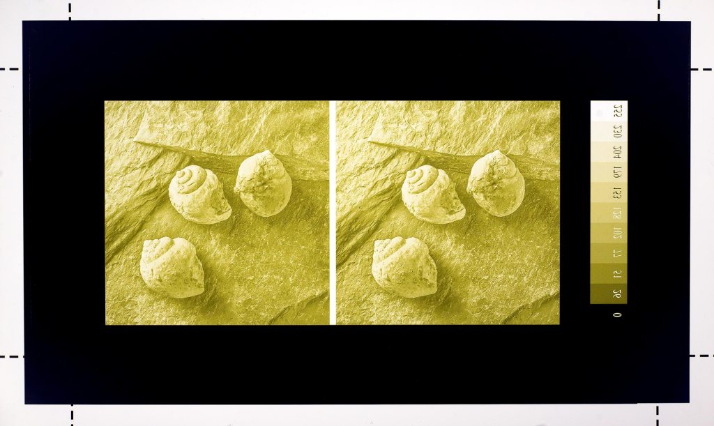
Nótese como la combinación de tintas empleada en la impresora de chorro de tinta confiere un tono claramente amarillo al fotolito impreso. Esta combinación de tintas se ha calibrado previamente como la que proporciona el mejor bloqueo de luz ultravioleta (UV) con la impresora, la tinta y la fuente UV empleadas (6-MIT). Una vez impreso el fotolito, el procedimiento es el habitual en fotograbado sobre plancha de cobre (5-MIT). Este trabajo se compone de tres estampas con los correspondientes pares estereoscópicos. Se titulan como Ammonoidea, Echinoidea y Gastropoda, tomando estos nombres de la clase o sub-clase de los fósiles mostrados en las respectivas imágenes.
5. Edición – Los heliograbados se han impreso en un número de tres, más una prueba de artista (AP). La Fig., 8 muestra una de las estampas finales. Las estampas están tituladas, firmadas y numeradas en caracteres romanos (I/III, II/III y III/III). Cada estampa incorpora en la parte inferior un gofrado en seco con el nombre del trabajo, XIX·XXI. El papel empleado es el Saunders Waterford Cold Pressed de 425g/m2 y la tinta es la Bone Black de Gamblin. La colección de los tres heliograbados, una hoja con una breve descripción del trabajo y un estereoscopio OWL de la London Stereoscopic Company se presentan dentro de un estuche de piel hecho a mano con cierre magnético (Fig., 9) y realizado por Santiago Lozano de Boltaña (Huesca). La tipografía del texto explicativo se ha realizado también mediante un proceso manual que se describe en el enlace Tipografía con Plancha de Magnesio.
Note as the inkjet printer ink combination has a yellowish hue. In this case, this is the better ink combination found in order to perform the best blocker to the UV light employed. Any UV light source should be calibrated on this way (6-MIT). With the positive transparency already printed, the procedure follows as is usual in heliogravure or photogravure on copperplate (5-MIT). This work is composed by three prints with the correspondent stereoscopic pairs. They are entitled as Ammonoidea, Echinoidea and Gastropoda, taking those names from the Class or Sub-class of the three fossils shown in the respective pictures.
5. Edition – The heliogravures have been printed in a number of three, plus one A/P (artist proof). The Fig., 8 shows one of the final heliogravure prints. The prints are entitled, signed and numbered in roman figures (I/III, II/III and III/III). Each print incorporates a dry embossing with the title of the project, XIX·XXI. The paper used is the Saunders Waterford Cold Pressed (425g/m2) and the ink the Portland Black from Gamblin. The collection of three different heliogravures, a print with a brief project statement and an OWL stereoscope from the London Stereoscopic Company are boxed in a handmade leather case provided with magnetic closure (Fig., 9) manufactured by Santiago Lozano from Boltaña (Huesca, Spain). The letterpress of the text sheet has been also handmade by a process described in the link Magnesium Plate Letterpress.
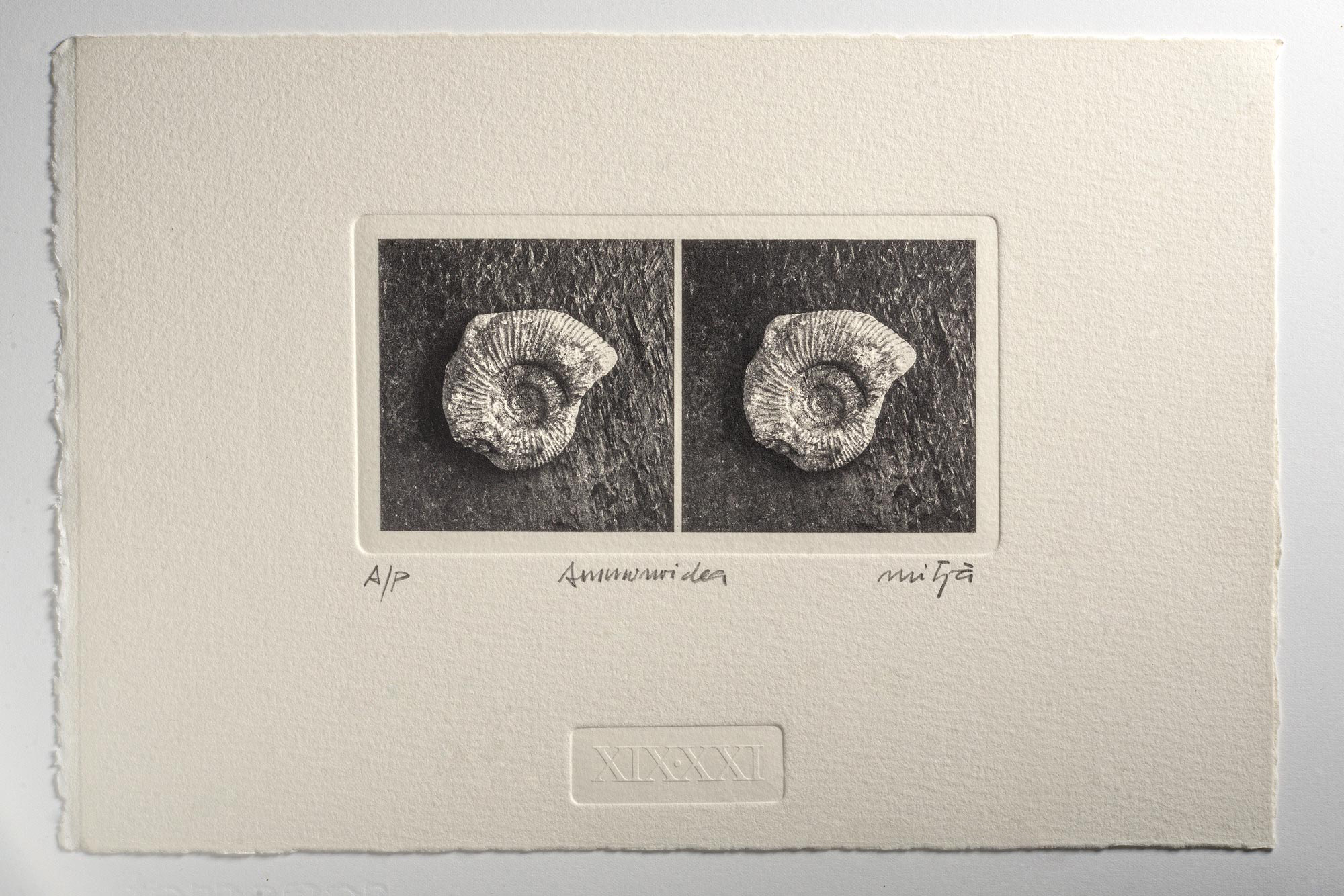

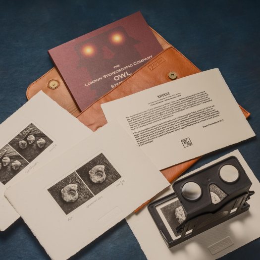
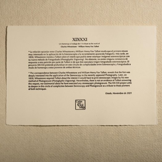
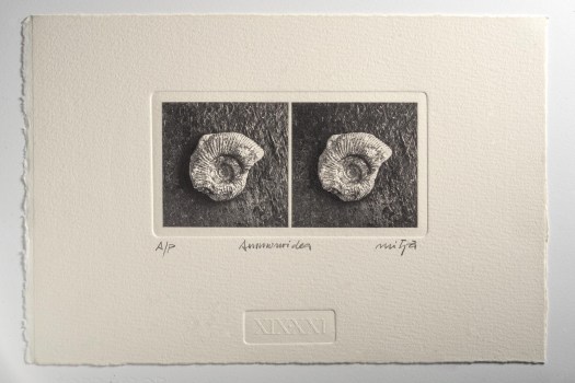
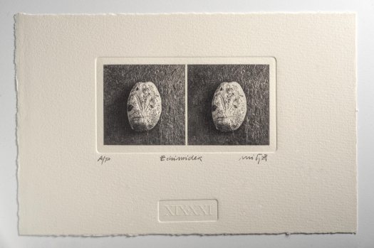
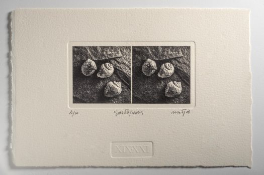
Figure 9 (click on any picture to access to a slideshow)
6. References
1. LINSSEN, E. F. (1952) STEREO-PHOTOGRAPHY IN PRACTICE, A Practical Guide for Photographers and Microscopists. The Fountain Press, London.
2. London Stereoscopic Company. OWL Stereoscopic Viewer. On line: https://shop.londonstereo.com/OWL-B-ENV.html Last review December 2021.
3. METHERELL, Colin (2017). Early 3D, The British Contribution to Early Stereoscopic Photography, on line: http://www.stereoscopicsociety.org.uk/WordPress/early-3d/ Last review December 2021.
4. MITJA, Carles (2013). Profundidad de Campo en Fotografía Digital (I). On line: https://carlesmitja.net/2013/05/19/profundidad-de-campo-en-fotografia-digital-i/ Last review December 2021.
5. MITJA, Carles (2016). A Hybrid Approach to Photogravure on Copperplate. On line: https://carlesmitja.net/2016/12/07/a-hybrid-approach-to-photogravure-on-copperplate/ Last review December 2021.
6. MITJA, Carles (2017). Printing Negatives or Positives for Alternative Processes. On line: https://carlesmitja.net/2017/08/24/printing-negatives-or-positives-for-alternative-processes/ Last review December 2021.
7. MITJA, Carles (2018). Image Processing for Hybrid Processes – Processing Raw Files. On line: https://carlesmitja.net/2018/01/01/image-processing-for-hybrid-processes-iv-processing-raw-files/ Last review December 2021.
8. SHAAF, Larry (2003). Etchings of Light, in Sun Pictures; Talbot and Photogravure. Hans Kraus Jr. Gallery, NYC.
9. WHEATSTONE, Charles (1838). Contributions to the Physiology of Vision – Part the First. On some remarkable, and hitherto unobserved, Phenomena of Binocular Vision. Philosophical Transactions of The Royal Society of London, Vol. 128, pp. 371-394.
10. WHEATSTONE, Charles (1840). The correspondence of William Henry Fox Talbot. Doc. Nº 4172. On line: http://foxtalbot.dmu.ac.uk/letters/transcriptDocnum.php?docnum=4172 Last review December 2021.
11. WHEATSTONE, Charles (1841). The correspondence of William Henry Fox Talbot. Doc. Nº 4198. On line: http://foxtalbot.dmu.ac.uk/letters/transcriptDocnum.php?docnum=4198 Last review December 2021.
12. WHEATSTONE, Charles (1858). The correspondence of William Henry Fox Talbot. Doc. Nº 7751. On line: http://foxtalbot.dmu.ac.uk/letters/transcriptDocnum.php?docnum=7751 Last review December 2021.

Excellent. A lesson of stereoscopy, a lesson of photography ( with a lesson of illumination) and finally a lesson of heliogravure, the most important. Lots and lots of good information and very good references. Congratulations. You can’t stop. I wish you continue by this way.
LikeLiked by 2 people
Thank you Jaume. With some help of you, too.
LikeLiked by 1 person